
I’m taking some initial steps toward working satellites this fall, and part of that crossed paths with dialing in my APRS setup, which led to me working the ISS digipeater with my homebrew copper cactus. While that worked, I was having deep fades and dropouts due to the vertical polarization of the J-Pole being incompatible with the right-hand-circular-polarization (RHCP) of the ISS system. This problem gets worse as the ISS rises in elevation relative to the ground station due to the deep overhead null in the vertical’s pattern.
Amateur Radio operators solve this issue in several ways: One is to track the satellite with a handheld linear-polarization antenna like a Yagi-Uda and manually rotate the antenna to match polarization and peak the signal; Another is to use a circularly polarized directional antenna and track the satellite manually or by rotator control; and then there is the omnidirectional RHCP antenna, of which the eggbeater is a common example. I am looking to operate from a fixed indoor location over the colder months, so I’m starting with the eggbeater.
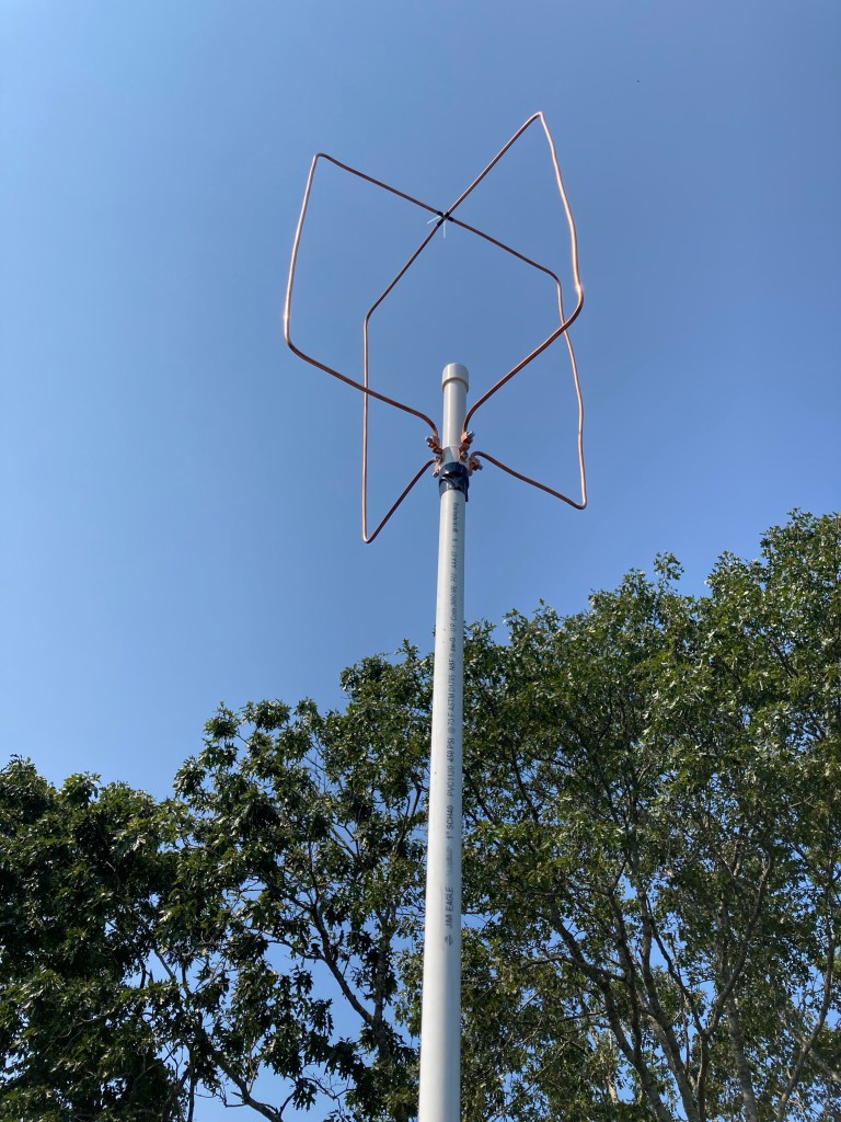
The eggbeater is a variant of the “turnstile” antenna, using two full-wavelength loops as the driven elements. The two loops are driven “in quadrature” using a section of coaxial cable to create a phase delay line, which creates the circular polarization pattern. I won’t reinvent anything here and I’ll direct you to the designer of the Eggbeater II variant, Jerry K5OE: Eggbeater II Omni LEO Antennas. I also highly recommend ZR6AIC’s article Building my Eggbeater II Omni LEO Antennas. I picked up several good ideas from his build.
The K5OE design is excellent and a great starting point for construction. It is a little light on the details which is great because each builder can come up with their own approach. I will demonstrate some of my construction techniques, my mistakes and corrections, and my impression of the overall performance.
Materials: I’m sticking with Schedule 40 PVC pipe/fittings, soft copper tubing, and easily available hardware. I’m using 1” pipe and fittings and it feels like the right move. The RF parts I used include low-loss coaxial cable, appropriate connectors, and a section of Belden RG-62 93-Ohm coaxial cable for the phasing line.
The RG-62 helps keep the SWR down as it is close to 100-Ohm and that plays nice with the goal of creating a 50-ohm feedpoint from two full-wave elements. If you want to build it with 75-ohm CATV coax your SWR might suffer a bit but it will still work. It might take some reverse engineering but pay attention to your cable’s velocity factor when sizing the phasing line. One thing to know about these other forms of coax is they are not designed for solder connections. CATV and video systems use a crimp connector and the bare center conductor may act as the connector’s “center pin”. Look at most any CATV F-style connector to see what I mean. The Belden RG-62 I purchased on eBay had a small wire conductor loosely run through a soft plastic tube acting as the dielectric. It does not like heat. Also, the single wire is weak compared to a stranded center conductor. I broke the first one I assembled and won’t be surprised when the next one breaks.
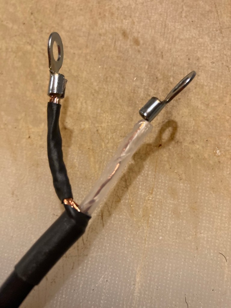
Here’s a tip: when you build the phasing harness mock it up and get the lugs oriented so they line up with the attachment screws. If you are twisting them into position they will break and the phasing line won’t lie nice and straight. You want it to fit nicely down the PVC support pipe.

One last detail: the antenna sits on a 4’ section of pipe with a T at the bottom. I run the feedline down the support pipe and out the side of a T fitting, and use another length of pipe below the T as a support. Cutting a 10’ length at the 4’ point is a good setup. You can keep an uncut 10’ length of pipe as a support if you need more elevation.
Assembly, The Driven Elements: The first obvious hurdle is the loop material. I decided to use 1/4” soft copper tubing based on price and the ability to bend it using a common handheld tubing bender. It feels like a compromise between weight and durability and worked out well in my build. The home-store refrigeration kits contain about 10 feet of tubing which is just enough to make the 2M Eggbeater, but the cost/foot is high. I went to my local plumbing supply shop and they had it for about $1/ft in a 50’ roll. I think that’s a better way to go, and if you have some left over you will have ideas for using it.
I used a $20 tubing bender from Home Depot. Get the type with registration markings and you will make accurate bends. Aligning your measurement marks with the “L” mark puts the mark about mid-bend. That worked perfectly in my build. Be sure to align the starting lines on the bender as well. Give yourself a few inches of slack at each end of the element and then trim the ends to size. The tubing has some give to make adjustments but the flatter you keep the element as you bend it the better.

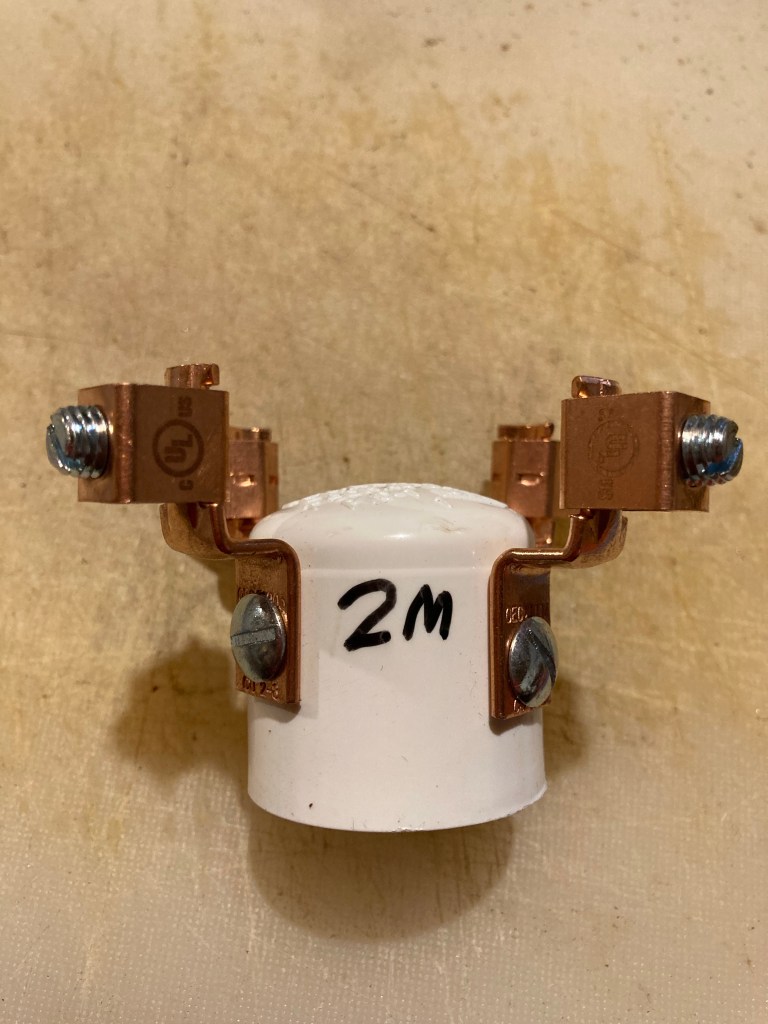
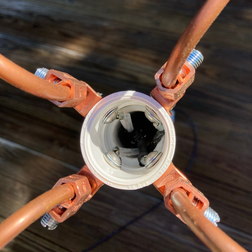
The next challenge is holding two big metal loops in a 90-degree orientation. I did some scrounging around the local home improvement megastore and landed on an offset ground lug from the electrical department. ZR6AIC mounts a similar lug to a 1” PVC cap. I tried this but my goal was to keep the phasing line inside the PVC and the connections prevented the cap from seating. I went with a 1” PVC coupler and mounted the lugs to the top half.


Did it work? Yes, it works very well, has great SWR, and the coverage during an ISS pass is greatly improved over a vertical antenna. I’m very happy with the final result. I’ll be making a 432 version next which will allow me to start monitoring linear sats with my IC705 and FT991A for uplink and downlink. I’m taking it slow with this instead of jumping right on and being a kook on the linear birds. I’ll still be a kook, but a slightly better prepared kook!
I estimate the costs at $50 per antenna. The tubing cost about $1/ft, the lugs and hardware are under $10, and the coax/connector is whatever you feel ok with. I used 10 feet of LM240 superflex and the DX Engineering 8X/240 crimp UHF connectors. You could buy a 20 foot premade jumper and cut it in half. You could make it with RG8X or RG58. For FM birds and ISS APRS it is not too critical. Getting correct polarization is the main benefit.
Feel free to ask me questions in the comments, or email me at n1qdq@petebrunelli.com. 73 and happy building!
