As 2022 draws to a close the amateur radio community was in a bit of shock as Yaesu announced that production of the FT-818ND will cease as well as the FTM-400XDE.
Greater minds than mine have paid homage to a classic:
On one hand it is sad because the FT-817/818ND has been and still is such a great radio for so many hams. I had owned three of them (maybe four) before buying a used 817ND in October as a portable LEO uplink radio. I now own a second one which I will not be parting with any time soon. I “speak Yaesu” having owned many Yaesu radios, and currently own two 817NDs, a FT-991A, a FTM-300D, and a FT3D. (I don’t have a problem, YOU have a problem!)
The 817/818’s low price, wide RX and TX coverage, and small size have made it the right rig for many purposes. The paired 817/818 (1634/1636) approach put thousands and thousands of QSOs in the logs of satellite ops. It has also been a mainstay in backpack/SOTA/POTA operations. They are found as IF rigs in many microwave stations. Even with the original battery it is one heck of a self-contained QRP radio. With one of the modern high capacity replacements it is even better. It is a natural for manpack operation with that front-mounted antenna connector. The one I recently purchased was in use as a bedside radio checking 80M and 40M net activity for a long time ham! It’s the Zelig of Amateur Radio.
They are known for durability, with some claiming they will be the cockroach of the used amateur transceiver market. They have an alloy chassis, metal covers, and a simple and not-fragile control/display cluster. The aftermarket has been very good to the 817/818, with all sorts of mounting, power, antenna, and user-comfort accessories available. A blind spot in the aftermarket is a reliable source of crystal filters. That would be a game changer. One of the rigs I owned about 15 years ago had both of them installed. Before the supply dried up. Kicking myself but that’s how it goes.
On the other hand this was predictable. Was it a perfect radio? Not even close. At its time of release it was known that the internal battery was garbage, the idle current was high, the power connector was terrible, the receiver was average (though not fatiguing) and it kinda needed those expensive optional crystal filters to be really useful, especially on CW. Oh, and the original FT-817 had an appetite for final output transistors. Even though the design and construction are more expensive now than they were 20 years ago the price has remained very stable. That’s not sustainable. The boards are full of discrete components, not offloading a lot of features onto a big CPU like you see on the Icom IC-705. It is a throwback radio in a world of muscled-up iPhones with an antenna connector.
I’ve written in this blog that I believe Yaesu is philosophically incapable of making a real competitor to the ICOM IC-705. They have doubled down so hard on HF+6 contest/DX radios and have gone so far away from the 817-type market that I don’t see them coming back. The 705 could be described as a 10W IC-7300 and a 10W ID-5100 shoehorned into a small box with a big display. It also uses a standard Icom battery. Brilliant. There really is no equivalent in Yaesu-world. Maybe a FTdx10 and FTM-300 mashup? Maybe I’ve just been juked too many times recently by Yaesu’s teasing of a groundbreaking new radio only for it to turn out to be the FTdx10, or the FT-710. The latter was especially tough because that was the rig I thought would be the IC-705 competitor and I could not have been more wrong.
I feel lucky to say that I run a 817ND and a 705 side by side in my LEO-bag rig, and it is an amazing contrast. I’d take the 705 receiver and DSP all day long, same for the built in recorder and the ICOM twin filter, but the simplicity of the 817ND and the flexibility, especially the dual antenna connectors, is unmatched in a shack-in-the-box rig. Once the noise dies down and the price gougers get their fill we can expect a long post-production lifespan fot these radios. Not unlike the ICOM IC-706/MKII a rig this capable will always be attractive.
Here’s to the little rig that could, and can, and will. Cheers.
Note: I got caught by COVID and am isolating, so now I’m getting caught up on blogging. Also focusing on keeping my wife safe and healthy while I get through this. It sux. No fun. I’m off the sats for a while while I recover. On with the blog.
Recap: My setup is a Yaesu FT-817ND and an IC-705 mounted in a backpack/sling-bag. The power source is a 8ah homebrew LiFePO4 battery. It isn’t especially lightweight but it is feature-rick thanks to the IC-705. In my setup the 817 is always the uplink rig. The 705 is always the downlink rig. All I do is switch coax connections when switching from U/V to V/U mode. I am 100% portable with no fixed antenna setup. That applies to all my amateur radio activities. I’m using my experience in VHF Rover contesting, hilltopping, portable QRP HF, and everything else to get up to speed on linear satellites.
I made my first QSO on a linear satellite in late October of 2022. I have had my fair share of learning experiences, setbacks, exciting contacts, and I learned a few things. Here’s a rundown of what issues I ran into, and how I resolved them.
Interference Issue: The immediate concern when I put the rigs together was the amount of noise the 705 was picking up on 70cm when transmitting on 2M with the 817. The 3rd harmonic of 145.960MHz is 437.880MHz. The 705 was receiving a big signal on 437.880, and it was crashing the front end of the 705. Normally the spur is not that big. This interference was preventing me from hearing the downlink when transmitting. Not a good place to be. Also, it is common to install a 2M low-pass filter to knock down any harmonics. Even with that It wasn’t helping. One reason for excessive spurs is an improperly biased or over-driven stage in the power chain. I finally bit the bullet and decided to re-set the bias on the 817’s power section. That’s an easy procedure than can be done with an ammeter. It made a huge difference. I’ll be adding a high-pass filter on the 70cm side, but for now the solution is good enough.
FT-817ND transmitting on 2M, 3rd harmonic received on the IC-705
Cable and connector choice: Aiming a handheld yagi at a briefcase-sized box hurtling through space is hard enough. You don’t want to make it harder. I make my own cable assemblies and usually have bulk cable on hand, along with connectors. My first set of cables was RG-8X with some decent BNC connectors. I was also using a right-angle Male/Female BNC adapter on the 817 and a coax jumper on the 705. My concern was minimizing stress on the radio connectors. The 705 has a BNC-F antenna connection on the side, and I didn’t want to run the coax through the shoulder bag.
While I was debugging the spur issue I stumbled over a high SWR issue. When I thought the 817 was in PWR-meter mode it was actually in SWR-meter mode, and it was showing high SWR. I made a simple SWR analysis of my cable runs using the SWR-meter mode on the 817, and did the same with my cross-needle SWR meter. The results were clear: BNC adapters can be a problem, especially at 70cm, Coax types like RG-58 and RG-8X are not great choices for this application, and I may have been having a high-SWR problem along with other issues causing my interference problem.
In 2021 I switched to Times Microwave LMR-240-UF (UltraFlex) for my VHF/UHF Rover setup, so I have plenty of it in bulk, and some good connectors. I built new 6-foot (2M) jumpers and ran them as directly as possible to the radios. For the 705 I built a short LMR jumper with BNC-right-angle on one end and BNC-F on the other, just long enough to get the connection above the radio. LMR-240-UF has low loss figures (much better than “HF” grade coax) and the cable has a foil shield between the braid and the dielectric; providing better shielding and less noise. It isn’t quite as flexible as other coax cables. I looked at Messi & Paoloni Hyperflex 5, which looks lighter, more flexible, and has great loss numbers. I’m not crazy about the connector selection, but it isn’t the worst. They have a BNCs in straight and right-angle.
Operating Locations: SO far I have mostly dealt with equipment, but what really makes a successful satellite pass is location. Having a good view to the horizon is essential for working low-elevation passes, and those passes are where the DX is. In VHF contesting I was primarily concerned with elevation. Height is might when choosing rover locations. And while a high location with panoramic views would be great but I live in coastal Rhode Island where there are few of those. What we do have is water, and a view over water is often good enough. I have found a few spots, though I am on a south-facing coast where views to the north, northeast, and northwest can be hard to come by. There are many tools you can use to scout locations. I have been using Google Earth for a long time. It shows elevation under the cursor, and has an elevation profiling tool as part of the line tool. HeyWhatsThat is another good tool for elevation profiles, I just haven’t figured out how to use it very well (yet).
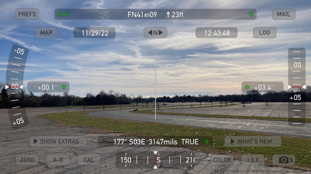
Funny Story! I often operate from Ninigret Park (within Ninigret National Wildlife Refuge) in Charlestown, RI which has a history as a naval air station, training field, and a bombing practice target. I use the GoSatWatch app for tracking passes and it usually does a good job in Sky View of showing the track of the bird and it will use the Apple compass to orient itself. Unless there is a unknown amount of ferrous metal under the parking lot! In an area I had chosen for it’s northeast view both GoSatWatch and Theodolite cant get a bearing fix, and it will swing wildly as I walk around. Aliens. I’m sure of it. But either way use mapping to get an idea of cardinal directions at your location because aliens could be throwing your fancy digital compass for a loop.
View to the South at Ninigret NWR
Another consideration is QRM/RFI. I had been using a parking area near the beach for because it was easy and had decent horizons. There was noise but I could work around it, until one day when the RFI was overwhelming. That was the first time I operated from there during the day. The noise was solar-panel inverter hash*. So that’s another consideration. Pointing a directional antenna at a residential area means you might be getting some of that junk in your receiver.
My home QTH isn’t all that bad for working satellites, especially now that the leaves are off the trees. Back we were looking for a home in coastal Rhode Island the realtor was showing us a variety of properties. Along with her choices, I was using Zillow to run searches and see what the market was like. One house kept popping up but the pictures were not great and I couldn’t tell what it really was… and is that a deck ON THE ROOF?
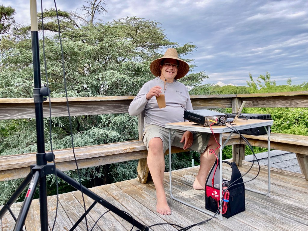
2022 June VHF on the Roof
The answer is yes, it has a deck on the roof. It makes for a nice spot to have a cup of coffee, do a crossword, freak out the neighbors, and mount antennas. My shack is 100% portable so I often mount a J-Pole, or my “armstrong” VHF stack, up there. It’s also where I set up my 991A/705 for my first linear sat contacts. I don’t have good sight-lines to the horizon, except to the SSE, but it is better than nothing. I do have a clear section to the northeast where I can work passes in the 8 to 10 degree and higher range. And if I have to work through the trees I will still make contacts, just not as many. This has been great for learning my way around the birds, working new grids, and I have even made some good contacts into Europe, Mexico, and the US West Coast from here. I can be QRV in a few minutes and it has been a great way to get on the air even if I don’t have a lot of time to spend.
A Wrap-up with some Tips:
Be patient while debugging problems in your system
Use the best cable and connectors you can manage
Whatever location you have access to is fine. Keep looking for good spots.
Whatever radio you have is good enough to get started. A few posts back I was building an Eggbeater Antenna for 2M because I was trying to work the ISS Digipeater. There are good ways to work simplex. A pair of HTs is a good FM setup.
I will always speak up for listening above transmitting. It is not easy to hold back on the PTT but there is a lot to learn by listening.
For your first contacts on linear satellites, find yourself on the downlink, get into a clear spot, and call CQ. This is much easier than getting on frequency with a calling station when you are starting off. Let the other op help you out. Just like juggling, start with two balls before you move on to three.
Since I don’t use any doppler-correction software I follow the “always tune the 70cm side” rule once I am on frequency. If I am on RS-44 I am tuning the 70cm downlink and keeping my 2m uplink fairly fixed. If I am on CAS-4B I am correcting the 70cm uplink and keeping the 2m downlink fixed.
I’ll be back in action once I recover from this bout of the ‘VID. See you on the birds. 73
*The worst part about this problem is that the remedy is cheap and easy. Chokes on the supply and distribution lines have been shown to be effective as the noise is radiated along the wiring. I was looking into solar panels for my home and asked the rep about RFI reduction and got a blank stare. It’s troubling how these devices are being deployed with no regard to their broadband RF emissions.