Category: satellite

  • CQ Satellite!

    CQ Satellite!

    RS-44

    I took the plunge into operating the amateur radio linear satellites a few weeks back and it has been a fantastic experience. My plan here on the blog is to share a few “blow by blow” accounts about what worked and what didn’t, what I have improved and how, and what’s next.

    Phase One – Get on The Air

    I’m a fan of “shack-in-a-box” radios so I already had the basic equipment necessary to operate on a linear-transponder LEO satellite. I used my Yaesu FT991A for the uplink, and my Icom IC705 on the downlink. Using the IC705 on receive made sense because the display on the IC705 is better, it has a built-in audio recorder, and it has options for things like bluetooth audio if I wanted wireless RX via earbuds, etc… I had to configure my station so I could manage two radios and point the antenna. I arranged the rigs so I could sit in front of them (I’m not hanging a 991A around my neck) and reach the tripod to point the antenna. I have a Heil Proset6 which I have used on the 991A so I had a wired solution for audio. I was not comfortable enough with the function of my internal “Profanity Suppression Module” (aka PSM) to use VOX, so I used the HEIL PTT trigger switch. This tied up my hands but I was mostly interested in tracking the satellite and finding the downlink.

    The antenna I use is an Arrow II, Initially I mounted it to a photo tripod so I could have some kind of sanity while I figured things out. It helped. I was able to track the bird and didn’t have much polarization-related fading. The Arrow is two antennas sharing a common boom, so there are two feedpoints. I purchased mine with the optional duplexer which turned out to be a good thing even if I am not using it as a duplexer. It can serve as a 2M Low-Pass Filter for 2M uplink, or a 70cm high pass filer, by only using half of the duplexer.

    I also have a ELK L5 LPDA that I have used often on VHF rover operations, fixed, and handheld. The Elk is a nice fit on the 991A for simplex operation because you don’t need a duplexer as long as you are working one band at a time To work full duplex I would need to split the feed with a duplexer, and I am not confident about noise rejection with both radios on a common feedpoint.

    That equipment made up Phase 1: two radios, hand mic, headphones, antenna on a tripod, iPad running GoSatWatch, and the appropriate page out of KE0PBR’s Satellite Cheat Sheet on a clipboard. That is a lot to manage at one time, especially while teaching myself how an inverting linear transponder works and how to operate through it. But those are the pieces-parts and I made exactly one QSO on a RS-44 pass on October 27th 2022. That first contact was not pretty but it did let me get my feet wet. I collected my thoughts and set up for the following pass and made seven contacts! I think that is still my best QSO/Pass figure.

    Once Phase 1 got rolling, I knew I needed to assemble a portable setup if I wanted to work sats on a regular basis. My home has a “crow’s nest” feature where I can walk up stairs to a small deck mounted on the roof. That’s a very good operating position and is also where I set up my portable V/U antennas for terrestrial operations. The downside is I don’t have a great horizon due to structures and trees. If I want a clear horizon I need to travel. Also, the setup/teardown for the 991A/705/camp table/tripod… is not practical. The good news is I was very close to having a portable solution. Yay.

    Phase Two – Portable Ops

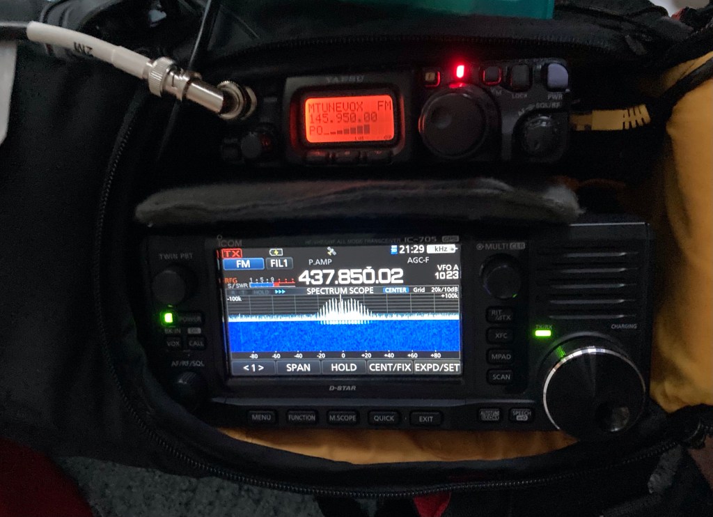
    One very common portable satellite station is a pair of Yaesu FT-817/818 radios (aka the FT-1634) in some sort of camera bag, and a few accessories to assist the operator. In my case I already have the deluxe option of the Icom IC705, and all I needed was a second rig. FT-817NDs are not too expensive so I began looking for one. I found a clean FT-817ND on QRZ.com for about $400 and got busy with the station-assembly phase. As an avid amateur photographer and I have a small collection of camera bags. The one that I settled on is a KATA 3N1-20 backpack/sling bag. Frankly, it was horrible for photography use and it has sat around unused for over 10 years. For radio purposes it is almost ideal!

    It has a large top compartment, while the main compartment has identical zippered access flaps on both sides of the bag. The symmetry of the bag means I can set it up to have full access to the rig fronts on one side, and full access to the rear on the other side, along with battery storage in the top lid. I used lots of “pluck apart” foam block to support and position the radios and built a simple fused power splitter to deliver 13.8v to both radios. The power harness is made from a factory IC705 power cable, plus some good 16ga zip-cord, and fitted it all with Anderson Powerpole connectors.

    For antenna connections I use a BNC pigtail to create strain relief and improve access to the IC705 antenna connector, and am building one for the 817ND. On the audio side I raided my parts bin and found a cheapie 3.5mm extension with a right-angle on one end to extend the headphone jack. On the 817ND I have the Heil AD-1-YM adapter fitted. Those give me the two connections I need to get audio to and from my Heil Proset 6. I’m running the 817ND in VOX mode now and rarely do I have a PSM glitch 🙂

    I love to build cables so I started off by making a set of 70-inch (1.7m) cables to reach from the Arrow II feedpoints to the radio. I actually staggered the lengths to compensate for the feedpoint locations so they terminate at about the same point. I used RG-8X to start with since it is cheap, I have it, and it would be good enough. Once I have the station dialed in I will make new jumpers with LMR-240-UF. I might use some double-shield RG-58 style cable for the pigtails. Having a flexible section of cable at rig is a good way to save wear and tear on the rig connectors. I also have to switch cables to switch modes as the 817ND is dedicated to uplink work.

    At this point I have a very good portable LEO station with the advantage of the IC705 on RX. That gives me things like built-in audio recorder, easy/excellent filtering and preamp controls, and a waterfall display to watch for my signal and others while operating. I have seen at least one ham running a pair of IC705’s but that is something I will think about for Phase III. The main advantage would be not having to switch antenna feeds when moving from a V/U bird to a U/V bird, and having the duplication of accessories and connectors. Maybe one day…

    Practical Issues

    Once I started using the 817ND/IC705 pair I was hearing/seeing a rise in the 70cm RX noise floor when I transmitted on 2M (U/V Mode B, used on RS-44), especially on voice peaks. My initial suspicions were RF in the power feed or the headphone cable, or a third harmonic spur from the 817ND. Putting chokes on the power and headphone cables was good for peace of mind, and may have helped a little (noise reduction?), but it didn’t solve the problem. I will post a more complete description of the issue later, but the 3rd harmonic of 146Mhz is 438Mhz. And dang if I couldn’t just tune to 438 and see that signal clear and loud! Ugh.

    Thus began a shakedown and testing program to either knock down the spurious signal or keep the third harmonic out of the 435MHz receive rig. My tools are the Arrow II duplexer, a Micro Circuits BLP-300+ LPF, and a HobbyPCB 2M bandpass filter. The best solution at first was using the Arrow II duplexer, connecting the common end to the radio and the 2M side to the 2M feedpoint. I installed a military surplus 5W BNC dummy load on the 435 side to keep things tidy in RF land. It’s not a bad solution, though I am thinking of building a high(er) performance 2M LPF that fits in the boom handle the way the Arrow duplexer does. I haven’t eliminated all of the crosstalk yet but a few changes have helped such as turning off the preamp on the IC705 and holding the antenna further from the radio while operating. I also assigned the BK-IN button on the IC705 to switch the preamp on/off so I can easily switch it while I operate. After initially using the duplexer as a LPF I am now using the Mini-Circuits BLP-300+. One reason is it makes the ARROW II much lighter and easier to point during a long pass, plus I found a cheap one on evilBay. It was actually a pull from a retired Piper aircraft! The standard choice for a LPF in this setup is the BLP-200+, and I have one ordered. We’ll see how that goes. The BLP-300+ only gives me about 38dB of attenuation at 438MHz, but it does help. I’m also not convinced that I don’t also have near-field RF from the 817ND.

    Working Portable Solution

    As of today the dust has settled and I am running the FT-817ND as my uplink rig, and the IC705 as the downlink rig, Heil PS6 headset, and an Arrow II with a Micro Circuits BLP-300+ low pass filter on the 2M side. I am using VOX with the headset plugged in to the IC705 audio output and the mic into the Heil adapter.

    So far I have made 73 contacts to 57 unique stations in 52 grids (41 confirmed), and feel like I am just scratching the surface.

    My North American gridsquares worked as of November 14, 2022

    Even with some bugs to work out I am able to operate on linear LEOs and my skills are growing with every pass. I owe a huge debt to the amateur satellite community for their resources and support. The operator resources provided by AMSAT are valuable and motivational, and the community on Twitter, the Groups.io FT817 group, and YouTube, are a veritable master class in LEO equipment and operation. See a future post for a resource listing and more complete shout-outs.

    I’ll close by saying I have not been as focused or obsessed over a ham radio project for a very long time. This is proving to be yet another collision of readiness and ability in my life. My fondness for VHF+, weak signal, portable operations has me right where I need to be. The fact that I have two HF+6+2+70 “shack in a box” radios made the initial foray into satellites possible. An understanding spouse has made it possible to make a concerted run at making this setup work in about three weeks of focused effort. See you on the birds! 73

  • Satellite Communications and the Void

    I often call Amateur Radio “the void” because it is an almost bottomless pursuit. I’ve been licensed for 30 years now and was lucky enough to fall in with an active ham radio club in Farmington, Connecticut, the Insurance City Repeater Club. They met at the Red Cross offices near UCONN Medical and that meant the ICRC met at the ICRC. Fun. The hams there were welcoming in most cases and the ones that I respected the most were very encouraging. This was the early years of the Volunteer Examiner (VE) program and they were both pushing new members to upgrade and letting them know that you could spend a lifetime exploring the privileges of the entry-level Technician license. I ended up earning an Amateur Extra license and becoming a VE. It was a good time to get into ham radio.

    Licensed hams have privileges on frequencies from VLF (below the AM broadcast band) to daylight. And daylight is not metaphorical. In the 10ghz and up world there are operators using coherent light generators to communicate over surprising distances. My path through ham radio has been fairly pedestrian with almost all of my activity on HF, VHF and UHF operation. Not that it is very limiting, but 440Mhz is not a very high frequency in the world of the electromagnetic spectrum. Sadly the frequency allocations above that see very little use, and there is precious little equipment on the market for those 1GHz and up frequencies.

    What you do on these frequencies is another matter entirely. Morse code, voice, various digital modes conveying text or images or data… There are many options and many ways to be involved in those options. I’ve played with all of those and unlike some hams I don’t pick favorites, or winners for that matter. It’s all good as long as you bring good operating practices to the party.

    I bring this up because I recently took the plunge into satellite communications. You can see from my Eggbeater Antenna posts I am talking about a very recent entry into satellites. More on that in the next post. But I bring it up because I was reviewing a recording of a RS-44 pass I worked and at the end I had a call from a station and then promptly lost touch with the sat. I sent him an email to let him know I heard him and I would listen for him in the future.

    This ham has been licensed for 9 months and dove directly into satellite communications. I wouldn’t be surprised if it was his main area of operation. That’s what you can do with a entry-level license with no Morse Code requirement. I can imagine that becoming a trend but for the current ham radio trend toward nostalgia. I think an operator who goes straight to the VHF+ arena is more likely to expand their activities up, toward daylight, than down. And that is a good thing. The more that happens the more the equipment market has a chance to react, and that brings in more users.

    I won’t go on a total rant, but the marketplace for ham equipment is clogged with the same gear that was popular 40 years ago and more. HF base stations, VHF/UHF mobiles, V/U handhelds, and some low-power kits and “fringe” radios. It’s nicer, shiny, and some of the modes have changed. That marketplace drives users when they pick up a magazine like QST and see it full of ads for that equipment. The VHF+ gear is limited, and presented as somewhat mysterious. The chicken-egg question is there, but we know that the manufacturers are the chicken, and the chicken is risk-averse.

    73, and keep looking up, toward daylight.

    Pete, N1QDQ

  • The Well Tuned Eggbeater

    The Well Tuned Eggbeater

    I’m taking some initial steps toward working satellites this fall, and part of that crossed paths with dialing in my APRS setup, which led to me working the ISS digipeater with my homebrew copper cactus. While that worked, I was having deep fades and dropouts due to the vertical polarization of the J-Pole being incompatible with the right-hand-circular-polarization (RHCP) of the ISS system. This problem gets worse as the ISS rises in elevation relative to the ground station due to the deep overhead null in the vertical’s pattern.

    Amateur Radio operators solve this issue in several ways: One is to track the satellite with a handheld linear-polarization antenna like a Yagi-Uda and manually rotate the antenna to match polarization and peak the signal; Another is to use a circularly polarized directional antenna and track the satellite manually or by rotator control; and then there is the omnidirectional RHCP antenna, of which the eggbeater is a common example. I am looking to operate from a fixed indoor location over the colder months, so I’m starting with the eggbeater.

    I know the reflectors are missing. Please use your imagination.

    The eggbeater is a variant of the “turnstile” antenna, using two full-wavelength loops as the driven elements. The two loops are driven “in quadrature” using a section of coaxial cable to create a phase delay line, which creates the circular polarization pattern. I won’t reinvent anything here and I’ll direct you to the designer of the Eggbeater II variant, Jerry K5OE: Eggbeater II Omni LEO Antennas. I also highly recommend ZR6AIC’s article Building my Eggbeater II Omni LEO Antennas. I picked up several good ideas from his build.

    The K5OE design is excellent and a great starting point for construction. It is a little light on the details which is great because each builder can come up with their own approach. I will demonstrate some of my construction techniques, my mistakes and corrections, and my impression of the overall performance.

    Materials: I’m sticking with Schedule 40 PVC pipe/fittings, soft copper tubing, and easily available hardware. I’m using 1” pipe and fittings and it feels like the right move. The RF parts I used include low-loss coaxial cable, appropriate connectors, and a section of Belden RG-62 93-Ohm coaxial cable for the phasing line.

    The RG-62 helps keep the SWR down as it is close to 100-Ohm and that plays nice with the goal of creating a 50-ohm feedpoint from two full-wave elements. If you want to build it with 75-ohm CATV coax your SWR might suffer a bit but it will still work. It might take some reverse engineering but pay attention to your cable’s velocity factor when sizing the phasing line. One thing to know about these other forms of coax is they are not designed for solder connections. CATV and video systems use a crimp connector and the bare center conductor may act as the connector’s “center pin”. Look at most any CATV F-style connector to see what I mean. The Belden RG-62 I purchased on eBay had a small wire conductor loosely run through a soft plastic tube acting as the dielectric. It does not like heat. Also, the single wire is weak compared to a stranded center conductor. I broke the first one I assembled and won’t be surprised when the next one breaks.

    One dressed end of the phasing harness.

    Here’s a tip: when you build the phasing harness mock it up and get the lugs oriented so they line up with the attachment screws. If you are twisting them into position they will break and the phasing line won’t lie nice and straight. You want it to fit nicely down the PVC support pipe.

    One last detail: the antenna sits on a 4’ section of pipe with a T at the bottom. I run the feedline down the support pipe and out the side of a T fitting, and use another length of pipe below the T as a support. Cutting a 10’ length at the 4’ point is a good setup. You can keep an uncut 10’ length of pipe as a support if you need more elevation.

    Assembly, The Driven Elements: The first obvious hurdle is the loop material. I decided to use 1/4” soft copper tubing based on price and the ability to bend it using a common handheld tubing bender. It feels like a compromise between weight and durability and worked out well in my build. The home-store refrigeration kits contain about 10 feet of tubing which is just enough to make the 2M Eggbeater, but the cost/foot is high. I went to my local plumbing supply shop and they had it for about $1/ft in a 50’ roll. I think that’s a better way to go, and if you have some left over you will have ideas for using it.

    I used a $20 tubing bender from Home Depot. Get the type with registration markings and you will make accurate bends. Aligning your measurement marks with the “L” mark puts the mark about mid-bend. That worked perfectly in my build. Be sure to align the starting lines on the bender as well. Give yourself a few inches of slack at each end of the element and then trim the ends to size. The tubing has some give to make adjustments but the flatter you keep the element as you bend it the better.

    HUSKY tubing bender

    The next challenge is holding two big metal loops in a 90-degree orientation. I did some scrounging around the local home improvement megastore and landed on an offset ground lug from the electrical department. ZR6AIC mounts a similar lug to a 1” PVC cap. I tried this but my goal was to keep the phasing line inside the PVC and the connections prevented the cap from seating. I went with a 1” PVC coupler and mounted the lugs to the top half.

    The PVC in the middle is just a scrap piece with a cap to close up the feedpoint. It could be much shorter, but this looks pretty badass.
    I tried using a cap, but it didn’t work. See the other pics and it shows how I used a coupler. Much better.
    These lugs are beefy and capture 1/4” copper tube perfectly
    Viewing the feedpoint from the top. The connections are in the top half of the coupler so the support gets a clean fit to the lower half.

    Did it work? Yes, it works very well, has great SWR, and the coverage during an ISS pass is greatly improved over a vertical antenna. I’m very happy with the final result. I’ll be making a 432 version next which will allow me to start monitoring linear sats with my IC705 and FT991A for uplink and downlink. I’m taking it slow with this instead of jumping right on and being a kook on the linear birds. I’ll still be a kook, but a slightly better prepared kook!

    I estimate the costs at $50 per antenna. The tubing cost about $1/ft, the lugs and hardware are under $10, and the coax/connector is whatever you feel ok with. I used 10 feet of LM240 superflex and the DX Engineering 8X/240 crimp UHF connectors. You could buy a 20 foot premade jumper and cut it in half. You could make it with RG8X or RG58. For FM birds and ISS APRS it is not too critical. Getting correct polarization is the main benefit.

    Feel free to ask me questions in the comments, or email me at n1qdq@petebrunelli.com. 73 and happy building!