Tag: antenna

  • How I learned to stop worrying and love the ICOM IC-9700 – Part 2

    How I learned to stop worrying and love the ICOM IC-9700 – Part 2

    Much like my interest in radio I’ve been playing musical instruments almost my entire life. We just used to be somewhat obsessed over the guitars, keyboards, amplifiers and eventually software that we saw on stage (on air) and in magazines. Eventually that got its own acronym G.A.S. for Gear Acquisition Syndrome. What I learned from years of horse-trading equipment via selling, buying, swapping, upgrading, downgrading… is that at some point I was very happy with my equipment and changing it around was a distraction. I play electric bass and usually am playing one of the four basses I own to the exclusion of the others. It might be a holdover from the many years when I had one bass, one amp, and not much else. Honestly I am a relentless pragmatist and mostly look for a piece of gear with certain capabilities. There have been… exceptions. Nuff Said.

    It has become the same thing with ham radio equipment. I moved around between many different radios and antennas in my first 10 years of ham radio operating. Mostly it was a need for a specific capability, like UHF all mode, or QRP HF with great CW chops. It was messy, and most of that gear is gone, but I learned a lot about what I do and do not like. I do still buy and sell things, but in the main I use the same gear for a long time. Time in the hobby helps you think “into the future” a bit and you can identify gear that will be junk soon, is junk now, is highly functional junk (heck yeah), or is the real deal. Spending time at hamfests is like a crash course. When I was an organizer for a small hamfest in Connecticut I was perusing somegrar at a table and one of the club “Elmers” buttonholed me and said “That rig was junk when it was new, and it hasn’t gotten any better. Talk to me later, but don’t buy it!” And we lear to sepeate the good from the bad (for our particular needs). There are radios that have very long useful lifespans (The FT-817/818, for example. The cockroach of the ham radio world.) and others that either have not or probably won’t.

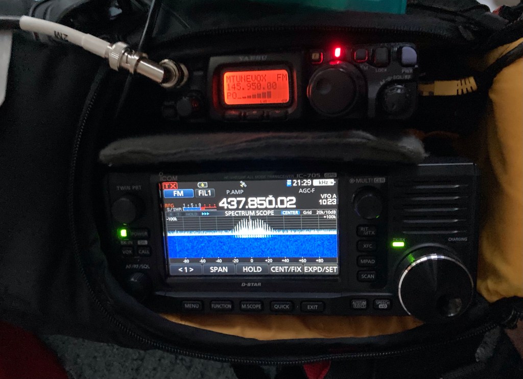
    Warning: The G.A.S. Monster is devious and does not sleep! Even as I started devoting more and more time to satellite operation I had resisted selling my FT-991A. It is a great radio. The ICOM IC-9700 is the only in-production V/U all mode with full duplex capability. That’s rare. There is usually competition in any given product segment. QRP radios, HTs, 100W entry level, Contest-focused rigs, HF linear amplifiers… There are choices. Not so in satellite ground station equipment. As I said in the last post, “One rig. That’s the list”. Meanwhile I am using my FT-817/IC-705 portable rig with a handheld antenna for all my sat work except for simplex digipeaters like Greencube/IO-117. I don’t know if I will ever put up a computer controlled alt-az antenna mount, preamps, etc… but I am interested in the capability. It was only a matter of time until I would decide to cut bait and obtain an IC-9700. May 2023 was that time.

    After a short flurry of sales activity on QRZ.com I had moved my Yaesu FT-991A and backup FT-817ND on to new loving homes, and had squirreled enough cash to blunt the not insignificant cash crater the purchase of a new IC-9700 would create. It’s the only game in town. There are no sales, incentives, or promotions worth mentioning. You want it, they have it, and if you don’t buy it someone else will. That, friends, is Scarcity Economics in action. So on to my preferred enablers at DX Engineering I went and plunked down the plastic for a IC-9700, a headset adapter, and the Icom/Electret variant of the dynamic-mic Heil Sound Proset 6 that I use on my portable rig (FT-817 is my uplink rig). The Pro-7 would give me better isolation, but I will take a lighter headset with some bleed when operating out in public. I can hear someone walking by or asking a question. That’s not a bad thing.

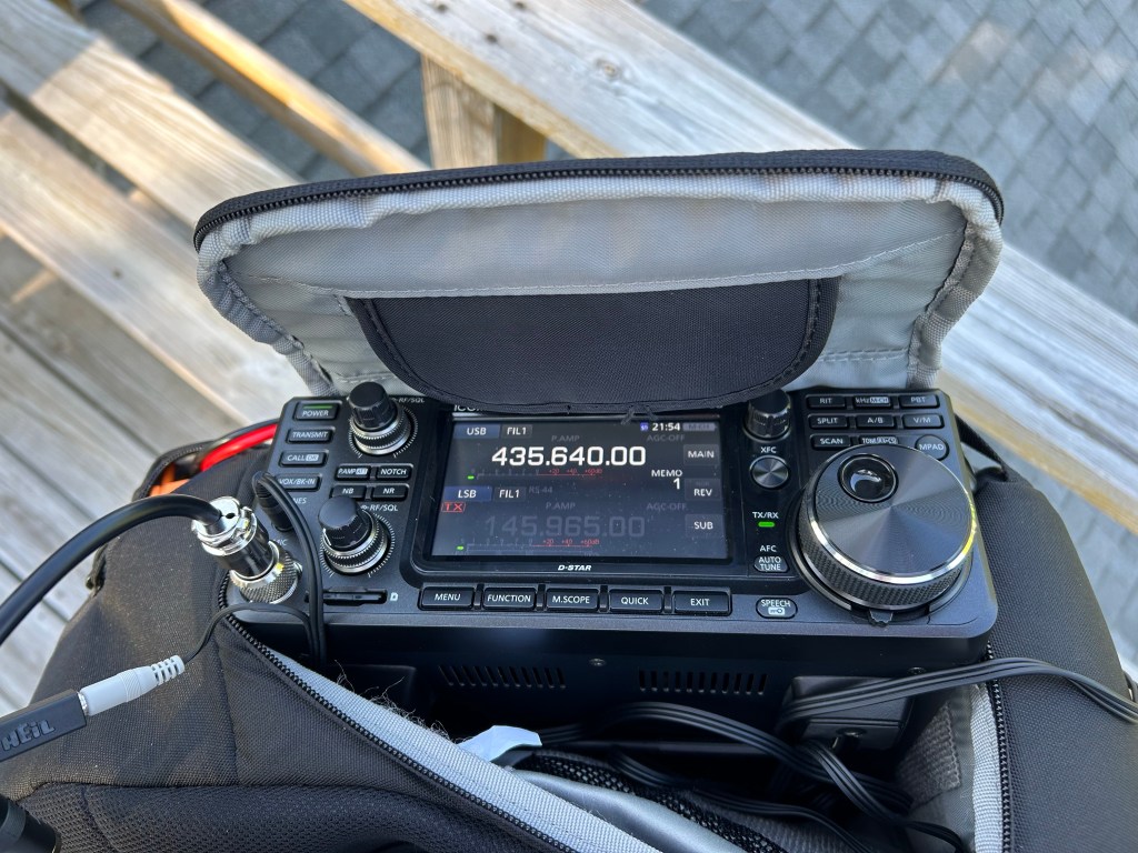
    It arrived quickly since DX Engineering is the king of getting the gear to your doorstep, pronto. First reaction: It’s a beautiful radio! I already had most of the power cabling I needed, along with N-Connector adapters, and it didn’t take me long to connect it to a dummy load and run through some menus. As I expected I felt right at home in the menu system. It is very similar to the IC-705. I also quickly noticed that the front panel is a bit cramped. Most modern radios have the same issue but I was thinking about using this radio outdoors, portable, and hitting the wrong control is something that just happens (foreshadowing).

    Some of the questions I had about operating this radio would only be answered through use. I have picked the brains of some very helpful satellite operators, and scoured the web for videos, but nothing gave me a clear idea of how this thing worked in comparison to my FT-817/IC-705 satellite rig. I am fully manual with that setup, tuning the uplink rig (817) and the downlink rig (705) separately. The waterfall display on the 705 makes finding myself on the downlink easy with little need for a cheat sheet. I know the transponder ranges and centers, and get within a few KHz right away. QSY is as easy as tuning the RX, having an idea of how far away I moved, then adjusting the TX the same amount (in reverse on a sat like RS-44. RX up 3, TX down 3…).

    The IC-9700 is different. It has a dual-VFO split mode and you can A/B between the two VFOs with dedicated touch screen buttons, using the main tuning knob to adjust each VFO one at a time. There is no sub-VFO control. There is RIT, but I am still not a fan of RIT for satellite work. My OCD tells me to just tune it correctly. I also won’t forget my RIT setting is on and waste time trying to figure out why I am out of band! That is similar to running two radios, but you only have one VFO knob.

    Then there is SAT mode. I figured this would be the “killer app” for tracking frequency on sats. You can activate either VFO, and there is a NOR (normal)/REV (reverse) button between the VFO buttons on the touch display. Sweet! (Reverse is where the input of the transponder and the output are reversed. The bottom of the uplink puts you on the top of the downlink, and as you tune the uplink higher your signal on the downlink tracks lower, and v-v)

    IC-9700 in a modified LowePro sling bag
    Rear Panel Access

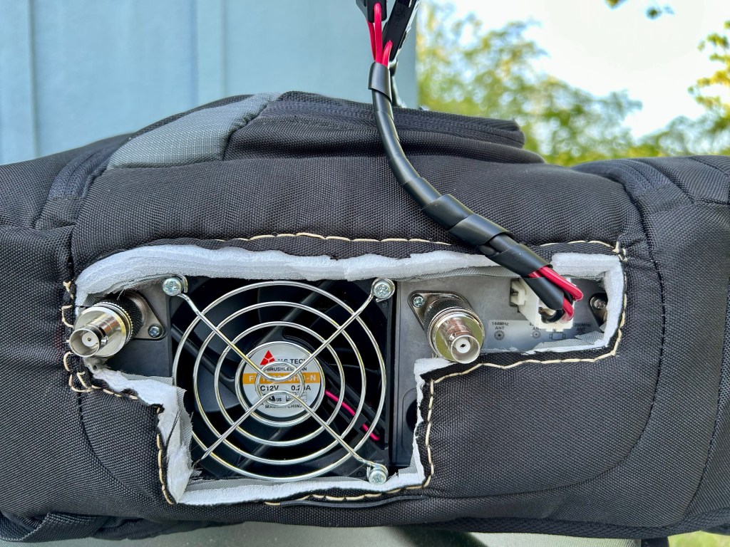
    I still use a handheld Arrow II antenna so operating sitting down is not a great option. Much like I did with my camera bag holster for the 817/705 rig I turned a LowePro sling bag that I had bought for a full-sized DSLR kit (and the bag was not great for that) and carved it up to allow me to wear the IC-9700. A Speedy-Stitcher made it easy to neaten up the cutouts I made for the rear connector access. I had to punch a hole through the side of the top compartment to snake the power lead out to the radio. Done. It worked and the rig only feels heavy, not unbearable. I hooked it up and went out to try a RS-44 pass. That’s a bird I am very comfortable on.

    I put the radio into SAT mode, set the VFOs, and off I went.

    Me and my Arrow

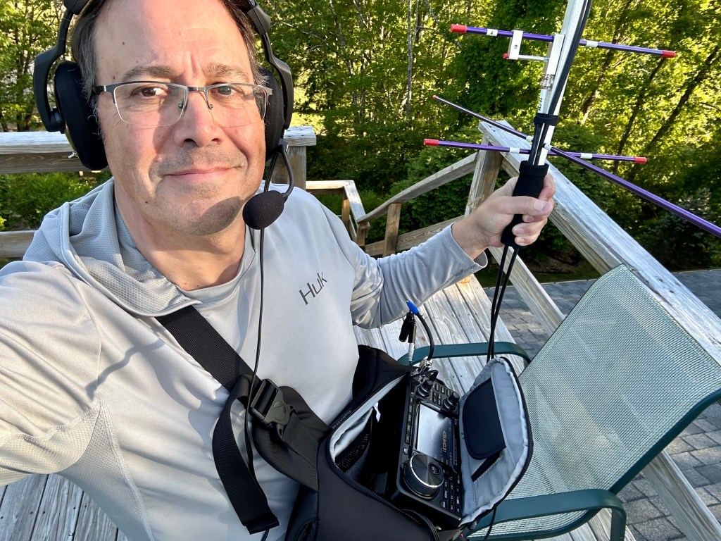
    Let’s just say it did not go well. I’m going to bullet list the things I tripped over because I think it will make it easier to convey:

    • Seeing the display in sunlight is very difficult. I will need t make a shade to use this reliably in this configuration.
    • Changing between VFOs is not as intuitive as I expected, and not hitting the NOR/REV pad by mistake is even harder.
    • If you press on one of the frequency displays the frequency is highlighted making it easier to see, but that does not select the VFO for tuning.
    • If you use the VFO Select pads you can select the correct VFO, but it doesn’t highlight the associated VFO display. There is also that NOR/REV button waiting for you to step on it like Sideshow Bob on a rake. So switching VFOs and being able to see the display in daylight is a two-press and check the status of the NOR/REV before proceeding. Every time.
    • Then there is VFO synchronization where neither VFO is selected and NOR/REV tells the rig how to sync the VFOs. Yes, it works. But as you QSY the tracking isn’t great and once you have the RX on frequency you now have to retune the TX VFO (or v-v) to get yourself back on frequency. So it works, but not well enough to just retune and hit the PTT.

    Admittedly I made it hard on myself by not doing more than a quick dry run before trying to make contacts with this radio. But I hope I am making the point that while the radio is a fantastic performer it seems more at home in a shack than hung around my neck. At the very least it will take practice to get to the point where manual operation is as intuitive as a dual-rig setup.

    My next mission was to get active on Greencube/IO-117. This turned out to be much more straightforward. Because the IC-9700 presents two virtual COM ports over USB I was able to run CI-V control on one and trigger PTT with the other. I use SATPC32ISS for the CI-V (CAT) control, and UZ7HO Soundmodem controls the PTT by directly addressing the higher-numbered of the two ports. I was able to get rid of the VSPE Virtual Port Splitter app I was using, and SATPC32ISS instead of HRD/HRD Satellite. That’s three open apps as compared to five which is a better place to be in the field when things inevitably go wrong.

    Greencube Portable Setup

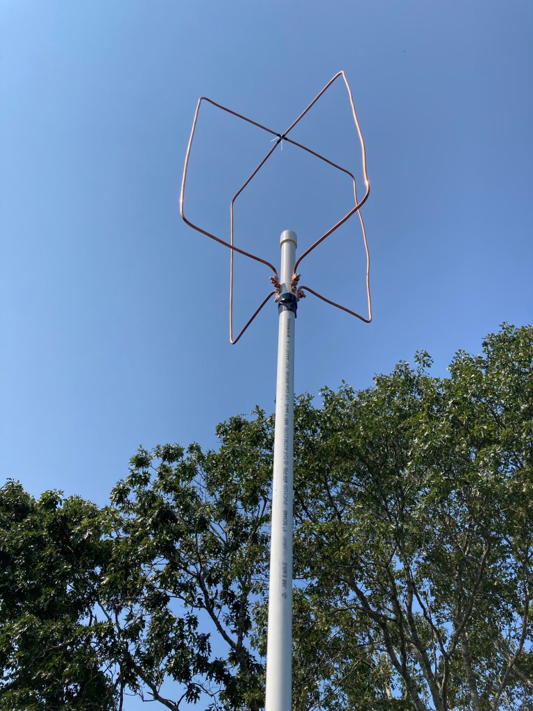
    It was as easy as the previous attempt was difficult. Using the same 70cm WIMO X-Quad I used with the 991A I was hitting IO-117 easily at 25w and made a few contacts immediately. Then “Greencube Hell” broke out and I wasn’t able to break in over the big signals is Europe and Russia. But it wasn’t due to a problem on my end. SUCCESS!

    After a few tries I was able to make SSB and FM LEO contacts with the IC-9700 in my portable setup. I was still getting tripped up a bit, but having the sats in memory banks and being able to switch between them that easily is very cool. I am still occasionally hitting NOR/REV by mistake and my next step is to just run it in dual-VFO Split Mode and see if that is easier. I think it will be.

    The performance of this radio is superb. Compared to the Yaesu FT-991A the receive sounds more sensitive and cleaner on weak signals. The 991A has a very good receiver, but there is something more “contrasty” about the RX on the 9700. The TX audio is levels above the TX audio on my FT-817ND. It is much punchier and clearer. You can pretty much tell a 9700 on the birds once you have used one. That is not a small detail when trying to make difficult contacts. Neither is the ability to dial up a few more watts when needed.

    One last thing before I close this and start thinking about Part 3:

    Even though the IC-9700 looks very much like the IC-7300 and IC-705 it is an older design and does not have features like Bluetooth Audio that I use all the time on the IC-705. Even if it was available I wouldn’t be surprised if it was left out to have one less RF source causing problems inside the IC-9700 chassis. It doesn’t feel as “fresh” as the IC-705 but maybe that is because I have a few years of 705 operation to rely on.

    Nobody has ever said the IC-9700 is a “field radio”. It is meant for the shack and if you take it into the wild there will be compromises. Little buttons, crowded display, not designed for cold fingers or no-look operation… But once it hooks up on a satellite it doesn’t matter. If we have only one choice in this category I am glad it is the IC-9700.

    Here’s the deal on not having the Yaesu FT-991A in my shack. I could easily see myself owning one again. It is a lot of radio for the dollar, epecially at the prices on the used market. As I have said on this blog, many people complain about the menus but how much time do you spend in the menus? The quick access menu takes care of day to day adjustments. I only had to go into the full menu to make major changes for data modes or filter ranges. The actual radio (not the feature set, the radio) is brilliant. It is a standout 100W HF rig with a great receiver, great on 6M, and the V/U performance is very usable. It isn’t a V/U thoroughbred like the 9700, but for most weak signal operation it is very good. I don’t work a lot of QRO HF, especially since getting set up for satellites, but I will miss a 100W HF rig at some point. The bigger miss is 6M. I like working 6M and this is a bad time of year to be without a 6M radio. My plan is to pick up a Yaesu FT-891 eventually and fill that void and have a portable QRO HF option.. Until then 10W on the IC-705 has been a good HF setup for me since I bought it, and it is still a great choice.

    More soon. Lots to learn about the 9700.

  • How I learned to stop worrying and love the ICOM IC-9700 – Part 1

    How I learned to stop worrying and love the ICOM IC-9700 – Part 1

    The Inevitable Happened…

    2023 marks 30 years of being a licensed ham and over that time I have owned a range of brands and types of radios, built QRP kits, built antennas… the usual stuff. I started out with a Ten Tec Triton IV, dial cord tuning, and that was a great rig. Excellent receiver, excellent QSK, great company. I ran a TT Scout for mobile HF and that was a fun radio. I liked the simplicity and the analog performance of those radios and can say I started off in ham radio as a “Ten Tec Guy”.

    Ten Tec 540 Triton IV w/ Analog Tuning

    But… I also have a “early adopter” streak, so I also bought an original Icom IC-706, then traded up to a MKII G when it came out. It was like buying a rig from the future! It may have been because the MKIIG is still a very good radio over 25 years later! Icom was ahead of the pack with the size and the feature set. The bleeding edge can be a good corner to hang out on.

    Later on my VHF Rover activities gave me a chance to use various Kenwood, Icom and Yaesu radios. They all had pros and cons. They all made plenty of contacts. Over the years I have owned a few of each, but on balance you could call me a “Yaesu Guy”. Yaesu vs Icom reminds me of Nikon vs Canon cameras. Yaesu is more like a Nikon, making great performing gear but holding on to a set of features and specs well past their due date. Icom is to me an equivalent to Canon. Canon always felt a little more flashy, more modern and easier to use, and Nikon was more old-school tried and true. Maybe Ten Tec was my Olympus, because I was a Olympus guy, who eventually became a Nikon guy, who became an Olympus guy again. It’s complicated! Like this analogy.

    A few years ago, after a bit of a layoff from ham radio, I had almost no gear left, and some accessories and a few HTs were all I had in my “shack”. I bought a Xiegu G-90 which is a very good radio, and a lot of fun, and it got me back on the air and active again. I also purchased a Yaesu FT-817ND because I have owned several before and I feel kinda “naked” without one. When I decided to get a 100W HF rig a few years back I realized that I needed VHF/UHF as well and the Yaesu FT-991A was the obvious choice. It covered VHF and UHF with some power, has a great receiver, and it has built in audio and and CAT over USB. After buying it I felt like I might have underestimated it. It is a better rig than I expected it to be. I have made loads of contacts with it. It is a 3-band VHF Rover rig, out of the box. I worked SSB, CW, RTTY, FT8, and other digimodes with ease. It’s also an excellent general coverage receiver and I did a lot of SWL with it.

    But a funny thing happened when Icom came out with the IC-705. The early adopter in me was back in charge. I bought one soon after it was released and I have been blown away by that radio. It has done everything the 991A has done, and more, with the trade off of less power against less weight. I used it for POTA, travel operation, mobile use, and then as half of my portable LEO satellite station. The 705 has been my downlink rig since I started satellite operation, and it is a joy to operate in that role.

    Icom IC-705

    You can see where this is going. Right now Yaesu is making a great line of HF radios, with several new models over the past five years, but the 991A is their only V/U All Mode, and there are no indications of anything new coming any time soon. The 991A is similar to the FT-817/818 in that it is an older design and the clock is ticking. Just this year Yaesu killed off the 817/817 line and Yaesu has not indicated that it will replace that radio. Meanwhile, the IC-705 showed me a better interface, better menus, and in many ways better performance in a very compact package. Certainly it is more convenient than the 991A and a technological leap beyond the Yaesu FT-817/818.

    In fact, I like the 705 so much that the 991A started to look like it might need a new owner. Between satellite operation and QRP the 991A wasn’t getting as much use. I never worried about the performance. It performs very well. Even the menu system isn’t that bad. It just isn’t great. And while it is a very good option for satellites like Greencube/IO-117 it isn’t full duplex and there is only one full duplex VHF/UHF All Mode currently in production, and it’s the Yaesu IC-9700. It might seem cliché for a sat op to run one but if you want the best satellite rig you can buy new the list is one rig long.

    So it happened… I sold both a backup Yaesu FT-817ND and the FT-991A and am now yet another sat op with a IC-9700! I have some immediate reactions from the first few days of ownership and I will cover them in the next post. Spoiler: Both the 991A and the 9700 are very good radios. They are also very different radios. And that’s a good thing.

  • Project Poutine!

    Project Poutine!

    In which I take N1QDQ international as N1QDQ/VE2 in eastern Quebec

    Over the past 15 years I have made many trips into eastern Canada, and most of those trips have focused on the Gaspe Peninsula. It is a lightly populated region with amazing culture, friendly people, great food, and stunning natural beauty. The peninsula is bounded by the St. Lawrence River on the north coast, the Baie des Chaleurs on the south coast, and the Gulf of St. Lawrence at the eastern end. The region is heavily francophone, and their dialect can be tough to understand even for other Quebecois. For me with my limited vocabulary, tin ear, and brutal American accent it is pretty much impossible. But on the other hand most Gaspesians will use whatever English they have to stop me from assaulting their language. When it comes to road signs, menus, basic written French… I can get by comfortably.

    As a satellite radio operator the attraction of the Gaspe is how few stations have contacted the region. Hams use a geographic system called the Maidenhead Grid Locator which organizes the planet by grids 2-degrees wide and 1-degree tall. In Rhode Island the whole state is in a Grid called FN41. The next grid square north is FN42, and the grid square to the east is FN51. Here’s an example:

    Maidenhead Grids – I live in FN41 in the bottom left of the image

    Hams collect contacts with these grid squares in a philately-like quest. Some grid squares are lousy with satellite operators. Even one or two active operators can make enough contacts to make that grid square commonplace. Other regions, and the Gaspe certainly fits this bill, have no operators at all. If you want a contact with that grid square then someone has to go there and “activate” it. That activity is called “roving”, and it is similar to the portable VHF contest activity I have done previously (also called a Rover station).

    With all of the travel restrictions over the COVID era I have not been there since the fall of 2019. My good friend Philippe lives there and we have both missed our time visiting either here in New England or there in Quebec. This put two trips I wanted to take in play as one single trip. A satellite rove to the Gaspe and time to spend with good friends in a great region of the world. Matane, Quebec is about 750 miles and 11-12 hours from my home in southern Rhode Island. My preferred route is to avoid Boston traffic and drive straight up US Interstate 91 through Connecticut, Massachusetts and Vermont, then to Drummondville, QC where the Trans-Canada Route 20 takes me 7 hours east to the Gaspe. The first goal is to get past Springfield, MA where the traffic calms down and the drive up the scenic Connecticut River Valley begins. Once across the Canadian border the terrain flattens and the English-speaking FM radio stations fade into the distance. Turning east at Drummondville, QC puts me on a not too pretty stretch of road that changes dramatically once I have passed Quebec City. From there it is a parkway through rolling farms, the St. Lawrence River, with the last gasp of the Appalachian Range ahead.

    The Gaspe Peninsula

    With all that preamble done, here is the radio stuff you probably came here for:

    The Plan:

    I brought equipment to work both Low Earth Orbit (LEO) satellites and the Greencube/IO-117 Mid Earth Orbit (MEO) digipeater satellite. The LEO rig is a Yaesu FT-817ND for the uplink and an ICOM IC-705 for the downlink. I use Micro-circuits filters on both antenna feeds, and an Arrow II dual band antenna. It is powered by a homebrew LiFePO4 battery pack and is easy to take on a short walk or easy hike. The main satellites I was interested in were RS-44, AO-7, SO-50, and the ISS.

    LEO operation above the St. Laurent in Matane, QC

    My MEO setup is not so portable. My newly acquired ICOM IC-9700, a 20Ah Bioenno LiFePO4 battery, my Dell Ultrabook, a WIMO 435MHz X-Quad, and a very brawny and old Gitzo photo tripod.

    My MEO/Greencube setup in use at Ninigret Park, Rhode Island

    These trips are easiest for me if I get a very early start, and on this trip it was wheels-up at 5:00AM. Once I made it to White River Junction, VT I stopped for a break and checked the satellite schedule. I saw a decent RS-44 opportunity at about 9:30 AM EST / 1330 UTC. Here is a good example of the challenge a big trip like this posed to me: How much time am I burning to work a satellite pass when it is part of a 12-hour drive? When I saw a pass that had good elevation, or was in part of the sky I expected to see clearly, the plan was to look for a spot starting about 10 minutes before AOS. I would simply keep driving if I ended up in some gorge, or blocked off by a mountain range.

    First Stop: RS-44 from FN34wa near Norwich, Vermont.

    Roadside rest stop in Vermont

    This is a roadside rest area and while it wasn’t amazing the pass was high enough to clear the short ridge to the west. I made 11 contacts and the site was fairly quiet. I was concerned about how much RF noise I would encounter at an interstate roadside. This one wasn’t bad even with traffic on the highway and the tractor-trailer that pulled in a parked right in front of me. Of course I was in rural Vermont and not on I-95 in the RF hellscape of Fairfield County, CT.

    Second Stop: IO-117/Greencube from FN45al near Sherbrooke, QC.

    Roadside operating location in Sherbrooke, QC

    There is a grid intersection in Sherbrooke where the Rt. 55 briefly loops from FN35 into FN45, but none of the gridline locations looked safe. I pulled off an exit and found a safe roadside spot in FN45 with a good view of the pass. It was also near the entrance to some kind of gravel/crusher operation because dump trucks full of that stuff kept rolling past. It was hot, dusty, and dry. But, I did put another 11 contacts into the log.

    Here’s my Greencube rant: I could have made many more contacts if it weren’t for the “ham radio stylings” of several operators. On a digipeater you are trying to get the sat to hear you, the retransmit your message. It is simplex, meaning it alternately receives or transmits on a single frequency. If you see your message come back then most of the other operators also saw your message. Job done. Or it should be. Several of the stations that kept calling me multiple times within each minute were taking the slots I needed to reply. Having one station doing that makes it hard to reply, and a few stations doing that made it impossible. These same stations were calling me, and THEN calling CQ in the next frame! EVERYONE SAW YOUR CALL. Why ask for more congestion when you are trying to make a contact? Also, the pass put the bird over Europe for the last half. These big-gun Europe and Russia stations have the sat at a very high elevation. I’m on a roadside running 25W off a battery and manually trying to keep the antenna pointed at the bird as it is at 20 degrees elevation and descending. My range to the satellite is at least twice what theirs is. And they keep big-footing the digipeater. I won’t go on, but I will say this about Greencube: Less Calling Equals More Contacts.

    As much as some ops have turned this bird into a cesspool of terrible operating practices, ahem, I was looking forward to using the huge footprint to contact hams in Japan, and South America, and the Middle East… Sadly there was a technical problem and Greencube stopped operating its digipeater just after this stop. It was inactive throughout my entire trip and would not be active until one week after my return. Good Grief.

    Stop #3: RS-44 from FN58oi, Le Bic, Quebec.

    Parc Nacional du Bic – Bic, QC

    In this case there was an eastern pass of RS-44 and I was passing one of the few stretches of the road where hills block the north and east. It looked like I might have to skip it but I was pretty sure the entrance to the SEPAQ park in Bic might have a view across the bay to the east/northeast. The question was if I would get there in time. I did, and it did. Again, 11 contacts! It had some power line QRM and the southeast part of the pass was blocked off by hills. After this is was time to pack up and finish the drive to Matane.

    La Baleine has welcomed visitors to Matane for over 50 years!

    I consider Matane the gateway between the Bas Saint Laurent (Lower St. Lawrence) region and the Gaspe-Peninsula proper. My perception is mostly about geography. Matane is the first of a long string of towns which sprung up where a river meets the sea. These were natural places for fishing, logging, transportation, and general commerce. The Matane river is a major salmon fishing destination and tourism hub, but is also a sleepy town with a few hotels and a nice centerville. Even if you just stop at La Fabrique microbrewery and gastropub it is worth it, but definitely take a walk by the river and see the port area.

    On my first day I experienced a trademark weather switcheroo. We went for an early afternoon hike in the interior above Rimouski and had at least 90F/35C and full sun. As soon as we headed back to the coast the view over the St. Lawrence River greeted us with a line of storms coming straight across from the north. Within hours the temperatures had dropped into the low 40F range and were still dropping. That weather even set the stage for a cold and wet visit.

    Riviere Rimouski – Portes de l”Enfer Canyon

    In Matane I scouted out an elevated spot above the Old Harbor which was good for seeing that big north horizon. The cold wind was a challenge which would continue for the most active part of the trip. This location in FN68 was my most productive as it was less than 10 minutes from the apartment and had parking spaces and a picnic table. Sometimes you take the easy spot and run with it. This was one of those times.

    A colder, wetter, me above the Old Port in Matane, QC

    With Greencube out of the picture I focused on RS-44, and looked out for AO-7 and ISS passes. The Matane stop was a good chance to recharge from the drive, and with the weather turning bad I wasn’t as active as I planned to be. Even with that I was sticking to my goal to move up the coast and activate FN69, FN79, and FN78. That drive just happens to be one of the most dramatic tours in Quebec. Even with the bad weather it was going to be a good drive.

    Finding public spots to make satellite contacts on the coastline can be a challenge as the road does not have many safe pull offs. With the SW-NE angle of the coastline it can be tough to find a clean look to the E-SE and SW looks are even rarer. Many of the passes I worked were partials. I could see the first half or the last half of the pass, but not both. Better than nothing! Narrowing down potential passes was straightforward. I looked for good direction, good/workable elevation, and good timing.

    Early the next morning I headed out to work two RS-44 passes in Matane, returning to warm up between passes. Then it was time to pack the car and start the trip to Riviere au Renard on the eastern tip of the Gaspe.

    An operating location in Grosses-Roches, QC
    I made a few contacts from the Phare at La Martre, QC

    I have been close but never actually visited Riviere au Renard before so all I had to go on was Google Earth and some photos from the web. I was excited to operate from here because the FN78/79 grid intersection runs right through the fishing port, and Google Earth made it look like the parking lot at the Auberge Caribou was on the gridline. I’d be having a comfortable activation and noshing on a chicken wing before sliding into my warm bed! Or so I thought.

    This was a LIE! The Maidenhead overlay I use in Google Earth is deeply flawed. While it shows the gridline in an easy spot it turned out to be slightly south of here. This miscue is also on me because the Lat/Long display in GE actually shows me that this displayed line is slightly north of the true line. NEVER TAKE EASY INFO AT FACE VALUE.

    The actual Gridline is HERE:

    Here’s the thing: I am very sensitive to property issues and avoid trespassing whenever I can. While wearing headphones, carrying two radios in a sling bag, and pointing an antenna, I’m even more sensitive. You never know what kind of reaction you will get from a homeowner even if you aren’t on their property (or are you?). The beach on the east side of the 132 is where I should have gone. BUT, long drives in bad weather combined with a focus on where I thought the line should be gave me a kind of tunnel vision. I walked out onto the seawall and kept going until I hit the gridline. This was stupid. I have spent a lifetime rock hopping on seawalls here in southern New England. It’s not like I had no idea what I was doing. But, this thing was a beast. It had much more in common (difficulty wise) with an alpine scree slope than a Rhode Island “breachway”.

    But I did it.

    Seawall Spot showing FN79ta
    Seawall Spot showing FN78tx

    I even missed the first part of the RS-44 pass while I slowly made progress until my iPhone GPS showed both FN79 and FN78. I finally got to the spot and I made a few RS-44 contacts. Then I saw an overhead ISS pass was starting right after RS-44. I’m there already. I’m cold. I’m wet. But I’m there. Why not! I’m so fried that even an FM sat looks like an oasis!

    And that’s when I worked astronaut @Astro_Woody Hoburg, operating as NA1SS on the International Space Station. To say it was surreal is an understatement. I was wet and freezing and trying my hardest to dodge the big splotches of seagull excrement that surrounded me. And then I’m talking to an astronaut. And then I’m not. And then I have to retrace my steps back to the shore. That is where the satellite portion of the evening ended. The next RS-44 pass was not going to happen. I needed to shower, eat, sleep…

    By the way, Au Frontibus microbrewery is the hot setup in Riviere au Renard. Relaxing, hot fresh food, and good beverages no matter your tastes. Even the soda selection is very good. Auberge Caribou was a good place to stay but I’d skip the restaurant. There aren’t many choices, but Frontibus turned out to be a better option.

    The next morning I had recovered enough and was still waking up very early. That happens to me on some trips, especially with an itinerary. At 0520 local I worked an RS-44 pass from the beach in front of the hotel in FN79. It was back to the hotel room to organize my gear and prepare for load-out. About 90 minutes later I made my way over to the port and worked the next RS-44 pass from a dock in the fishing port in FN78. That’s more like it. No ankle-breakers and bird bombs. The weather was still foul, I was still very cold and exhausted, but at least I wasn’t slipping on seagull poo.

    A hot breakfast at the Croque-Faim restaurant, a hot-ish shower, and I was ready to hit the road back to Matane. I think the return trip is somehow even more dramatic than the trip out there. There are sections where you crest a rise in the road and the view is literally breathtaking. The massive St. Lawrence spreading out to the horizon, a tiny church spire on the shore below.

    Grande-Valee, QC

    Just west of Riviere au Renard is a small one of these crests, and there is a safe pull-off on the north side of the road. I used that spot for several passes, with its open view to the west and north. The photo below shows north but I think it is actually a but more west. The compass in my iPhone was unreliable in many spots. I’ve seen this at Ninigret Park in Rhode Island, an ex military air base with who knows how much ferrous and copper buried beneath the surface. For whatever reason I had a devil of a time getting compass bearings and resorted to maps with fixed north if I had cellular data available.

    My operating spot above Petit-Cap, QC

    An early pass there was nice and quiet, but the pass I worked on my way out of town was a mess of wall to wall white noise. I am pretty sure someone was welding nearby. It wasn’t crackly or fluctuating. It was just +20 white noise, then off, then on, then off… Just like someone laying down beads with a MIG welder. I still made contacts, and I took the approach of transmitting during the noise. I don’t need to hear myself and it increased the odds of a reply happening during an “off” period.

    One very cool characteristic of the Gaspe is the lack of RF interference. In most areas you will hear four FM stations at most, and the cellular comms density is very low. In an area where I would be deafened by broadband noise, solar inverters, bad lighting transformers, etc… it was some of the quietest VHF/UHF conditions I have operated in.

    The run back to Matane was still cold, but the sun came out and the Saturday traffic was light. It took me half the time to get back as it took to get out there on a wet Friday.

    In the end I made 157 QSOs to 16 countries, contacted 82 separate grids, and activated seven grids (FN34, 45, 58, 68, 69, 78 and 79). This was my first rove and it was a trial by fire. My VHF contesting experience came in handy when managing the pileups and scouting for clear operating locations. The added logistics of finding appropriate pass times and trying to get to the right location at the right time were more difficult. On my outbound trip to Riviere au Renard it took over five hours. My Time-Speed-Distance (TSD) approach was down the drain. The return took three hours. Same deal. It’s either operate on the move, or hunker down. Doing both is a lot to manage.

    Another major factor on a long trip like this is fatigue management. My trip from RI to Matane was 14 hours, and about 750 miles, including the three stops for satellite work. That requires some recovery time. I don’t want to have an accident or make a bad decision because I am exhausted. I was also there to visit a friend, so satellite passes were secondary at various times.

    My great friend Philippe and I rid the oceans of the dastardly Moule, one Frite at a time!

    My return to Rhode Island was an uneventful 12 hours on the road, carrying many great memories and knowing that I have to be OK with how everything worked out. A major satellite in my plan conked out. I was not as fresh as I thought I would be and the cold and wet really took some of the energy out of me. My take-away is that I could have spread out stays over more locations and felt less exhausted and less rushed. But I also know I had a great time and found some kind of balance between satellites, rest and relaxation, and driving. I hope to be back there in a few months and will at least have my LEO setup with me. I hope it happens and I hope to get more of these grids into the logbooks of my fellow satellite operators.

    Acknowledgements:

    I’d like to thank everyone who supported me with education, information, kind words, and encouragement. John VE1CWJ, Ian K5ZM, John KG4AKV, and Jerry W8LR were huge sources of support as I prepared to leave on this trip. Carsten OZ9AAR, Peter G0ABI, and Peter 2M0SQL were reliable voices as I did my best to activate these grids. The Ham Twitter community at large was massively supportive and I couldn’t have done it without them. Considering that I started working satellites in October 2022 it was a steep learning curve and many hams were there with patience and great information. 73

  • Thoughts About Birds

    Satellites, that is.

    This post is a follow up to my LEO Learning Curve post from earlier this month. I think of this as sharing some notes, providing context, and trying to make them readable for others.

    One thing you can’t rush is experience. You can prepare, study, make notes, organize information, and so on, but nothing is a substitute for putting in the time. In my case it is about 6 months since my first satellite QSO, so I’m not speaking from great authority. I am speaking to others who are starting to work sats, are thinking of it, or are frustrated by it.

    Here are a few things that have helped me:

    • Take a Listen-First approach to your satellite passes: Running two VFOs on a sat pass can be like juggling at first. Just like juggling it helps to start simple before adding balls in the air. Track the doppler shift of a satellite for fun, listen to the stations they are working and how on-frequency they are/are-not. Having some practice with the receive side makes it easier to find yourself and track shift during a QSO.
    • There is no “One True Rule”: Correcting for Doppler shift isn’t done the same way by all operators. I have had some odd experiences where the other station is off frequency but copying me, and when I retune to hear them they chase me. I assume they are using RIT, which is weird on SSB, but . They could also be using computerized doppler correction and adjusting both uplink and downlink at the same time. I understand the approach, but it only works if both stations are doing it the exact same way. (I assume these are computer control guys who are warm in their shack while I am shaking in the cold and trying to tune with numb fingers.)It is difficult to make a contact a contact if the other station isn’t tracking Doppler shift the same way. Leaving the 2m side alone and tuning the 70cm side to correct for Doppler is how I roll. Either way, listen and you can hear one or both stations fine-tuning.
    • Start with more passes and then find better passes: When looking for an operating location, start by finding a convenient spot to where you live/work and try that first. An easy location with just-ok horizon can be an excellent spot to build technique. I use an app like Theodolite to document the cardinal directions and the height of the horizon due to obstructions. Make a little map, maybe. You can now use that to decide whether a pass will be worth setting up for. Or find a pass on the edge and see what you can hear and how well you can hit the satellite (or hear yourself).
    • Satellites Helping Satellites: Use a tool like Google Earth to scout locations with a clear horizon, especially to the east or west. Piggybacking on the previous item, I have found some excellent spots precisely because I needed to work a low-elevation pass to work a station in Europe or on the West Coast of the US. GE has Street View, and the line tool generates a terrain profile. Draw a line from your spot to the direction you want to work and see what it looks like. You can also drop to ground level and see the estimated horizon. It’s usually very close. I use Google Earth (or other mapping if you want) to scan for good locations.
    • Refine your portable locations: I have fine tuned one of my Greencube/IO-117 operating locations for Northwest-AOS passes this way and have a good number of JA stations to show for it. Here is the Google Earth Screenshot:

    Both of these lines show a 320-degree bearing at Ninigret Park in Charlestown, Rhode Island FN41ei. The line from Location 1 has a radio tower right on the 320-deg bearing, and some higher/closer trees. I used GE to find Location 2, where 320-deg is on the right side of some trees, but there are fewer obstructions, the radio tower is comfortable off to the north, and the trees are further/lower. This small change of just a few hundred yards got me into IO-117 earlier/lower in the pass and allowed me to contact more JA stations on these passes starting between 220-230 degrees AOS and running overhead to south-east to about 160-degrees at LOS.

    • All Is Not Equal: The correlation between how loud you are hearing yourself on the downlink and how loud the other station is hearing you on the downlink is “loose”. I often hear myself at true 59 on RS-44 and the other stations is not able to copy me. That could be polarization and antenna selection, the location of the other station, receiver type, preamps… That situation works both ways. A weak station might be hearing you very well while you can barely hear yourself. Just try to make the QSO. I record my passes and have exchanged recordings. It is interesting to hear what the other station is hearing.
    • Make skeds! I’ve been able to help other ops get closer to WAS because they needed Rhode Island, or FN41. It doesn’t seem rare but I have had plenty of European ops interested/scheduled. This little state has plenty of hams but not many on the sats. I went a long time with only one contact in FN41 and it took me a while to get it confirmed! Likewise, look for operators or rovers in grids and states you need. Many grids are only available this way as they have no resident operators.
    • Keeping track of uplink and downlink pairs: I have a document in a notes app on my phone with just the basic transponder info and it is very handy. If you use a downlink radio with a waterfall display you can get away with only keeping a note of the uplink and downlink center frequencies, transponder bandwidth, inverting/not, and doppler shift direction. You will use the waterfall to spot yourself, and if you correct manually for doppler you will be only tracking the 70cm radio most of the time. I use GoSatWatch or one of the other iOS apps for tracking passes, so having a transponder reference document on my phone is super helpful.
    • Keep an open mind about everything: I would like to finish this list with a shout out to Dragan, 4O4A, who tweeted this super helpful doppler correction procedure. Knowing the upper and lower limits of the uplink and downlink, plus the doppler offsets, is all you need. My mind is still a bit blown, but it is changing how I will approach the previous tip. For 2023 I will be making a passband-edge and offset document for the linear sats I like to work.

    How I approach a typical pass, and some other considerations:

    Take RS-44, an inverting V/U satellite with decreasing doppler tracking, for example: My uplink is a Yaesu FT-817ND, set to 2M LSB, and I run it in VOX mode with a headset. My downlink is an Icom IC-705, in 70cm USB mode, and the waterfall set at 50KHz wide. I have a pretty good idea of UL/DL frequencies at or near AOS. Once I hear the bird well enough I will whistle and look for my signal on the waterfall. When I find it I move my DL frequency to a quiet section and move my uplink to match. That’s a good place to start calling CQ. I also might start by listening to the frequencies I “see” on the IC-705 waterfall. It gives me a quick idea of who is active and who they might be working. At that point I can call one of those stations, or move to a quiet spot to call CQ. I might do that several times over 5-10 minutes. I might make three or four CW calls, then scan the stations again.

    When I need to QSY I know my TX has to move the same amount (in reverse) as my change in downlink frequency (and v-v). If I move my receive frequency from 435.650 to .655 I have to move my uplink down (inverting) by 5KHz.

    On an overhead pass it is important to remember it’s a low elevation pass for someone. In my area that can be the Rockies and upper Midwest USA, through central Canada, or could also be Mexico and Central America. It’s easier for me to work those stations on a pass with a 35-50 degree W or S max elevation, especially since my home has a bad western view.

    So that’s what I have found useful as I started operating more satellite passes, and putting time into optimizing my routine. Drop a comment or an email if you find this useful, or have something to add. Best 73 and see you on the birds, Pete N1QDQ

  • 2022 News Flash – Yaesu FT-818ND Discontinued

    2022 News Flash – Yaesu FT-818ND Discontinued

    The Golden Retriever of the Amateur Radio World

    As 2022 draws to a close the amateur radio community was in a bit of shock as Yaesu announced that production of the FT-818ND will cease as well as the FTM-400XDE.

    Greater minds than mine have paid homage to a classic:

    K4SWL at QRPer.com

    OH8STN recounts his feelings here

    A thread on the SOTA.uk board

    And EI7GL pays tribute

    On one hand it is sad because the FT-817/818ND has been and still is such a great radio for so many hams. I had owned three of them (maybe four) before buying a used 817ND in October as a portable LEO uplink radio. I now own a second one which I will not be parting with any time soon. I “speak Yaesu” having owned many Yaesu radios, and currently own two 817NDs, a FT-991A, a FTM-300D, and a FT3D. (I don’t have a problem, YOU have a problem!)

    The 817/818’s low price, wide RX and TX coverage, and small size have made it the right rig for many purposes. The paired 817/818 (1634/1636) approach put thousands and thousands of QSOs in the logs of satellite ops. It has also been a mainstay in backpack/SOTA/POTA operations. They are found as IF rigs in many microwave stations. Even with the original battery it is one heck of a self-contained QRP radio. With one of the modern high capacity replacements it is even better. It is a natural for manpack operation with that front-mounted antenna connector. The one I recently purchased was in use as a bedside radio checking 80M and 40M net activity for a long time ham! It’s the Zelig of Amateur Radio.

    They are known for durability, with some claiming they will be the cockroach of the used amateur transceiver market. They have an alloy chassis, metal covers, and a simple and not-fragile control/display cluster. The aftermarket has been very good to the 817/818, with all sorts of mounting, power, antenna, and user-comfort accessories available. A blind spot in the aftermarket is a reliable source of crystal filters. That would be a game changer. One of the rigs I owned about 15 years ago had both of them installed. Before the supply dried up. Kicking myself but that’s how it goes.

    On the other hand this was predictable. Was it a perfect radio? Not even close. At its time of release it was known that the internal battery was garbage, the idle current was high, the power connector was terrible, the receiver was average (though not fatiguing) and it kinda needed those expensive optional crystal filters to be really useful, especially on CW. Oh, and the original FT-817 had an appetite for final output transistors. Even though the design and construction are more expensive now than they were 20 years ago the price has remained very stable. That’s not sustainable. The boards are full of discrete components, not offloading a lot of features onto a big CPU like you see on the Icom IC-705. It is a throwback radio in a world of muscled-up iPhones with an antenna connector.

    I’ve written in this blog that I believe Yaesu is philosophically incapable of making a real competitor to the ICOM IC-705. They have doubled down so hard on HF+6 contest/DX radios and have gone so far away from the 817-type market that I don’t see them coming back. The 705 could be described as a 10W IC-7300 and a 10W ID-5100 shoehorned into a small box with a big display. It also uses a standard Icom battery. Brilliant. There really is no equivalent in Yaesu-world. Maybe a FTdx10 and FTM-300 mashup? Maybe I’ve just been juked too many times recently by Yaesu’s teasing of a groundbreaking new radio only for it to turn out to be the FTdx10, or the FT-710. The latter was especially tough because that was the rig I thought would be the IC-705 competitor and I could not have been more wrong.

    I feel lucky to say that I run a 817ND and a 705 side by side in my LEO-bag rig, and it is an amazing contrast. I’d take the 705 receiver and DSP all day long, same for the built in recorder and the ICOM twin filter, but the simplicity of the 817ND and the flexibility, especially the dual antenna connectors, is unmatched in a shack-in-the-box rig. Once the noise dies down and the price gougers get their fill we can expect a long post-production lifespan fot these radios. Not unlike the ICOM IC-706/MKII a rig this capable will always be attractive.

    Here’s to the little rig that could, and can, and will. Cheers.

  • CQ Satellite!

    CQ Satellite!

    RS-44

    I took the plunge into operating the amateur radio linear satellites a few weeks back and it has been a fantastic experience. My plan here on the blog is to share a few “blow by blow” accounts about what worked and what didn’t, what I have improved and how, and what’s next.

    Phase One – Get on The Air

    I’m a fan of “shack-in-a-box” radios so I already had the basic equipment necessary to operate on a linear-transponder LEO satellite. I used my Yaesu FT991A for the uplink, and my Icom IC705 on the downlink. Using the IC705 on receive made sense because the display on the IC705 is better, it has a built-in audio recorder, and it has options for things like bluetooth audio if I wanted wireless RX via earbuds, etc… I had to configure my station so I could manage two radios and point the antenna. I arranged the rigs so I could sit in front of them (I’m not hanging a 991A around my neck) and reach the tripod to point the antenna. I have a Heil Proset6 which I have used on the 991A so I had a wired solution for audio. I was not comfortable enough with the function of my internal “Profanity Suppression Module” (aka PSM) to use VOX, so I used the HEIL PTT trigger switch. This tied up my hands but I was mostly interested in tracking the satellite and finding the downlink.

    The antenna I use is an Arrow II, Initially I mounted it to a photo tripod so I could have some kind of sanity while I figured things out. It helped. I was able to track the bird and didn’t have much polarization-related fading. The Arrow is two antennas sharing a common boom, so there are two feedpoints. I purchased mine with the optional duplexer which turned out to be a good thing even if I am not using it as a duplexer. It can serve as a 2M Low-Pass Filter for 2M uplink, or a 70cm high pass filer, by only using half of the duplexer.

    I also have a ELK L5 LPDA that I have used often on VHF rover operations, fixed, and handheld. The Elk is a nice fit on the 991A for simplex operation because you don’t need a duplexer as long as you are working one band at a time To work full duplex I would need to split the feed with a duplexer, and I am not confident about noise rejection with both radios on a common feedpoint.

    That equipment made up Phase 1: two radios, hand mic, headphones, antenna on a tripod, iPad running GoSatWatch, and the appropriate page out of KE0PBR’s Satellite Cheat Sheet on a clipboard. That is a lot to manage at one time, especially while teaching myself how an inverting linear transponder works and how to operate through it. But those are the pieces-parts and I made exactly one QSO on a RS-44 pass on October 27th 2022. That first contact was not pretty but it did let me get my feet wet. I collected my thoughts and set up for the following pass and made seven contacts! I think that is still my best QSO/Pass figure.

    Once Phase 1 got rolling, I knew I needed to assemble a portable setup if I wanted to work sats on a regular basis. My home has a “crow’s nest” feature where I can walk up stairs to a small deck mounted on the roof. That’s a very good operating position and is also where I set up my portable V/U antennas for terrestrial operations. The downside is I don’t have a great horizon due to structures and trees. If I want a clear horizon I need to travel. Also, the setup/teardown for the 991A/705/camp table/tripod… is not practical. The good news is I was very close to having a portable solution. Yay.

    Phase Two – Portable Ops

    One very common portable satellite station is a pair of Yaesu FT-817/818 radios (aka the FT-1634) in some sort of camera bag, and a few accessories to assist the operator. In my case I already have the deluxe option of the Icom IC705, and all I needed was a second rig. FT-817NDs are not too expensive so I began looking for one. I found a clean FT-817ND on QRZ.com for about $400 and got busy with the station-assembly phase. As an avid amateur photographer and I have a small collection of camera bags. The one that I settled on is a KATA 3N1-20 backpack/sling bag. Frankly, it was horrible for photography use and it has sat around unused for over 10 years. For radio purposes it is almost ideal!

    It has a large top compartment, while the main compartment has identical zippered access flaps on both sides of the bag. The symmetry of the bag means I can set it up to have full access to the rig fronts on one side, and full access to the rear on the other side, along with battery storage in the top lid. I used lots of “pluck apart” foam block to support and position the radios and built a simple fused power splitter to deliver 13.8v to both radios. The power harness is made from a factory IC705 power cable, plus some good 16ga zip-cord, and fitted it all with Anderson Powerpole connectors.

    For antenna connections I use a BNC pigtail to create strain relief and improve access to the IC705 antenna connector, and am building one for the 817ND. On the audio side I raided my parts bin and found a cheapie 3.5mm extension with a right-angle on one end to extend the headphone jack. On the 817ND I have the Heil AD-1-YM adapter fitted. Those give me the two connections I need to get audio to and from my Heil Proset 6. I’m running the 817ND in VOX mode now and rarely do I have a PSM glitch 🙂

    I love to build cables so I started off by making a set of 70-inch (1.7m) cables to reach from the Arrow II feedpoints to the radio. I actually staggered the lengths to compensate for the feedpoint locations so they terminate at about the same point. I used RG-8X to start with since it is cheap, I have it, and it would be good enough. Once I have the station dialed in I will make new jumpers with LMR-240-UF. I might use some double-shield RG-58 style cable for the pigtails. Having a flexible section of cable at rig is a good way to save wear and tear on the rig connectors. I also have to switch cables to switch modes as the 817ND is dedicated to uplink work.

    At this point I have a very good portable LEO station with the advantage of the IC705 on RX. That gives me things like built-in audio recorder, easy/excellent filtering and preamp controls, and a waterfall display to watch for my signal and others while operating. I have seen at least one ham running a pair of IC705’s but that is something I will think about for Phase III. The main advantage would be not having to switch antenna feeds when moving from a V/U bird to a U/V bird, and having the duplication of accessories and connectors. Maybe one day…

    Practical Issues

    Once I started using the 817ND/IC705 pair I was hearing/seeing a rise in the 70cm RX noise floor when I transmitted on 2M (U/V Mode B, used on RS-44), especially on voice peaks. My initial suspicions were RF in the power feed or the headphone cable, or a third harmonic spur from the 817ND. Putting chokes on the power and headphone cables was good for peace of mind, and may have helped a little (noise reduction?), but it didn’t solve the problem. I will post a more complete description of the issue later, but the 3rd harmonic of 146Mhz is 438Mhz. And dang if I couldn’t just tune to 438 and see that signal clear and loud! Ugh.

    Thus began a shakedown and testing program to either knock down the spurious signal or keep the third harmonic out of the 435MHz receive rig. My tools are the Arrow II duplexer, a Micro Circuits BLP-300+ LPF, and a HobbyPCB 2M bandpass filter. The best solution at first was using the Arrow II duplexer, connecting the common end to the radio and the 2M side to the 2M feedpoint. I installed a military surplus 5W BNC dummy load on the 435 side to keep things tidy in RF land. It’s not a bad solution, though I am thinking of building a high(er) performance 2M LPF that fits in the boom handle the way the Arrow duplexer does. I haven’t eliminated all of the crosstalk yet but a few changes have helped such as turning off the preamp on the IC705 and holding the antenna further from the radio while operating. I also assigned the BK-IN button on the IC705 to switch the preamp on/off so I can easily switch it while I operate. After initially using the duplexer as a LPF I am now using the Mini-Circuits BLP-300+. One reason is it makes the ARROW II much lighter and easier to point during a long pass, plus I found a cheap one on evilBay. It was actually a pull from a retired Piper aircraft! The standard choice for a LPF in this setup is the BLP-200+, and I have one ordered. We’ll see how that goes. The BLP-300+ only gives me about 38dB of attenuation at 438MHz, but it does help. I’m also not convinced that I don’t also have near-field RF from the 817ND.

    Working Portable Solution

    As of today the dust has settled and I am running the FT-817ND as my uplink rig, and the IC705 as the downlink rig, Heil PS6 headset, and an Arrow II with a Micro Circuits BLP-300+ low pass filter on the 2M side. I am using VOX with the headset plugged in to the IC705 audio output and the mic into the Heil adapter.

    So far I have made 73 contacts to 57 unique stations in 52 grids (41 confirmed), and feel like I am just scratching the surface.

    My North American gridsquares worked as of November 14, 2022

    Even with some bugs to work out I am able to operate on linear LEOs and my skills are growing with every pass. I owe a huge debt to the amateur satellite community for their resources and support. The operator resources provided by AMSAT are valuable and motivational, and the community on Twitter, the Groups.io FT817 group, and YouTube, are a veritable master class in LEO equipment and operation. See a future post for a resource listing and more complete shout-outs.

    I’ll close by saying I have not been as focused or obsessed over a ham radio project for a very long time. This is proving to be yet another collision of readiness and ability in my life. My fondness for VHF+, weak signal, portable operations has me right where I need to be. The fact that I have two HF+6+2+70 “shack in a box” radios made the initial foray into satellites possible. An understanding spouse has made it possible to make a concerted run at making this setup work in about three weeks of focused effort. See you on the birds! 73

  • The Well Tuned Eggbeater

    The Well Tuned Eggbeater

    I’m taking some initial steps toward working satellites this fall, and part of that crossed paths with dialing in my APRS setup, which led to me working the ISS digipeater with my homebrew copper cactus. While that worked, I was having deep fades and dropouts due to the vertical polarization of the J-Pole being incompatible with the right-hand-circular-polarization (RHCP) of the ISS system. This problem gets worse as the ISS rises in elevation relative to the ground station due to the deep overhead null in the vertical’s pattern.

    Amateur Radio operators solve this issue in several ways: One is to track the satellite with a handheld linear-polarization antenna like a Yagi-Uda and manually rotate the antenna to match polarization and peak the signal; Another is to use a circularly polarized directional antenna and track the satellite manually or by rotator control; and then there is the omnidirectional RHCP antenna, of which the eggbeater is a common example. I am looking to operate from a fixed indoor location over the colder months, so I’m starting with the eggbeater.

    I know the reflectors are missing. Please use your imagination.

    The eggbeater is a variant of the “turnstile” antenna, using two full-wavelength loops as the driven elements. The two loops are driven “in quadrature” using a section of coaxial cable to create a phase delay line, which creates the circular polarization pattern. I won’t reinvent anything here and I’ll direct you to the designer of the Eggbeater II variant, Jerry K5OE: Eggbeater II Omni LEO Antennas. I also highly recommend ZR6AIC’s article Building my Eggbeater II Omni LEO Antennas. I picked up several good ideas from his build.

    The K5OE design is excellent and a great starting point for construction. It is a little light on the details which is great because each builder can come up with their own approach. I will demonstrate some of my construction techniques, my mistakes and corrections, and my impression of the overall performance.

    Materials: I’m sticking with Schedule 40 PVC pipe/fittings, soft copper tubing, and easily available hardware. I’m using 1” pipe and fittings and it feels like the right move. The RF parts I used include low-loss coaxial cable, appropriate connectors, and a section of Belden RG-62 93-Ohm coaxial cable for the phasing line.

    The RG-62 helps keep the SWR down as it is close to 100-Ohm and that plays nice with the goal of creating a 50-ohm feedpoint from two full-wave elements. If you want to build it with 75-ohm CATV coax your SWR might suffer a bit but it will still work. It might take some reverse engineering but pay attention to your cable’s velocity factor when sizing the phasing line. One thing to know about these other forms of coax is they are not designed for solder connections. CATV and video systems use a crimp connector and the bare center conductor may act as the connector’s “center pin”. Look at most any CATV F-style connector to see what I mean. The Belden RG-62 I purchased on eBay had a small wire conductor loosely run through a soft plastic tube acting as the dielectric. It does not like heat. Also, the single wire is weak compared to a stranded center conductor. I broke the first one I assembled and won’t be surprised when the next one breaks.

    One dressed end of the phasing harness.

    Here’s a tip: when you build the phasing harness mock it up and get the lugs oriented so they line up with the attachment screws. If you are twisting them into position they will break and the phasing line won’t lie nice and straight. You want it to fit nicely down the PVC support pipe.

    One last detail: the antenna sits on a 4’ section of pipe with a T at the bottom. I run the feedline down the support pipe and out the side of a T fitting, and use another length of pipe below the T as a support. Cutting a 10’ length at the 4’ point is a good setup. You can keep an uncut 10’ length of pipe as a support if you need more elevation.

    Assembly, The Driven Elements: The first obvious hurdle is the loop material. I decided to use 1/4” soft copper tubing based on price and the ability to bend it using a common handheld tubing bender. It feels like a compromise between weight and durability and worked out well in my build. The home-store refrigeration kits contain about 10 feet of tubing which is just enough to make the 2M Eggbeater, but the cost/foot is high. I went to my local plumbing supply shop and they had it for about $1/ft in a 50’ roll. I think that’s a better way to go, and if you have some left over you will have ideas for using it.

    I used a $20 tubing bender from Home Depot. Get the type with registration markings and you will make accurate bends. Aligning your measurement marks with the “L” mark puts the mark about mid-bend. That worked perfectly in my build. Be sure to align the starting lines on the bender as well. Give yourself a few inches of slack at each end of the element and then trim the ends to size. The tubing has some give to make adjustments but the flatter you keep the element as you bend it the better.

    HUSKY tubing bender

    The next challenge is holding two big metal loops in a 90-degree orientation. I did some scrounging around the local home improvement megastore and landed on an offset ground lug from the electrical department. ZR6AIC mounts a similar lug to a 1” PVC cap. I tried this but my goal was to keep the phasing line inside the PVC and the connections prevented the cap from seating. I went with a 1” PVC coupler and mounted the lugs to the top half.

    The PVC in the middle is just a scrap piece with a cap to close up the feedpoint. It could be much shorter, but this looks pretty badass.
    I tried using a cap, but it didn’t work. See the other pics and it shows how I used a coupler. Much better.
    These lugs are beefy and capture 1/4” copper tube perfectly
    Viewing the feedpoint from the top. The connections are in the top half of the coupler so the support gets a clean fit to the lower half.

    Did it work? Yes, it works very well, has great SWR, and the coverage during an ISS pass is greatly improved over a vertical antenna. I’m very happy with the final result. I’ll be making a 432 version next which will allow me to start monitoring linear sats with my IC705 and FT991A for uplink and downlink. I’m taking it slow with this instead of jumping right on and being a kook on the linear birds. I’ll still be a kook, but a slightly better prepared kook!

    I estimate the costs at $50 per antenna. The tubing cost about $1/ft, the lugs and hardware are under $10, and the coax/connector is whatever you feel ok with. I used 10 feet of LM240 superflex and the DX Engineering 8X/240 crimp UHF connectors. You could buy a 20 foot premade jumper and cut it in half. You could make it with RG8X or RG58. For FM birds and ISS APRS it is not too critical. Getting correct polarization is the main benefit.

    Feel free to ask me questions in the comments, or email me at n1qdq@petebrunelli.com. 73 and happy building!

  • That went about as well as I expected

    Scallop roll at Two Little Fish, Westerly RI. Sand Pail Ale by Grey Sail Brewing, Westerly RI. Photo: Pete Brunelli c2022

    How’s Your Summer Goin’?

    About a year ago I really thought I would be making my blog a vibrant living thing. But here’s the reality: You know those people who buy gym memberships and never go to the gym? This is like that except without the drain on my personal credit, and without the guilt. For myself and many others social media has largely usurped blogging. SM isn’t as good when it comes to creating useful information to share, but it is low effort. That often/typically makes it low quality as well. One look at any forum on groups.io (and many more) will demonstrate that.

    Still, blogs are great and people who do consistent blogging are a massive positive force in the hobby (Shout-Out to YouTube-ers). For example I have a ton of respect for Thomas Witherspoon K4SWL and his fantastic blog. I also get a lot of enjoyment out of it. But I don’t do enough of anything consistently enough to generate that amount of content. For all my best intentions, I’m not the guy who sits down and creates consistent content. Thomas is that guy. Thanks, Thomas!

    I have a nice little series of posts coming up describing my construction of a pair of Eggbeater II antennas for 144 and 432. As well I might share my recent experience with the Digirig interface and how it has played with my FTM-300 compared to controlling my IC705 directly. Why am I going down that rabbit hole? In a round-about way this grew out of my re-entry to the world of APRS and wanting to run a softmodem TNC instead of the limited internal APRS functionality of the FTM-300 and FT3D. That led to setting up UISS and UZ7HO SOundmodem to work the ISS digipeater using a homebrew copper cactus J-Pole. It’s OK at low angles but the polarization is all wrong. Lots of deep fades as a result, so it’s a very poor hit ratio. SO yeah, setting up an APRS station got me excited about sats as well.

    Homebrewing a pair of satellite antennas is the next natural step. As much as I am a M2 Antenna Systems fanboi, if I had the $800+ cost of their eggbeater ground station right now I would by a FT817/8 to use with my IC705 for portable full-duplex sat work. Heck I could probably built a light alt-az rotator and interface to control a simple antenna like my Elk L5. Could still happen.

    It’s a fun project so far.

    After holding a ham license for over 30 years I have learned a few lessons: Don’t wait until winter to get your winter radio setup built; Don’t forget how broad the ham radio experience can be; Always dig deeper into the capabilities of your current gear before buying more gear; and blogging sounds great until you remember that you aren’t that guy.

    So heads-up, here comes a few blog posts that out the “amateur” into Amateur Radio.

    73, Pete N1QDQ

  • Lightweight Antenna Roundup 2 – Chameleon MPAS Lite v Wolf River Coils SB1000 TIA

    When I was running mobile HF in the 1990’s and early 2000’s I accumulated a bunch of 3/8-24 mount antennas. There were hamsticks, Hustler coil-loaded whips, an Outbacker Perth, plain whips… Outbacker sold a metal tripod that was marketed as a ground plane and antenna mount in one. I didn’t spring for that. I just bolted a 3/8″ coupler to a cut-down surveyor’s tripod, made a quick and dirty radial plate, and gave it a go. It worked. It wasn’t great but it gave me a different way to deploy those mobile-mount setups. At that time these “stationary mobile” solutions were a novelty setup among the hams and publications I interacted with. A simple dipole was always going to crush that mobile antenna, and did.

    FFW to the vaguely 2020-ish period and somehow ultra-portable field antennas, mainly for QRP use, are flying off the shelves. In the depths of a solar minimum, no less. The effectiveness of these systems is a tribute to the radio arts in general. Getting a signal onto the air is still job #1. The vagaries of propagation and the system on the other end of the QSO take care of the rest.

    Three of the most popular categories today are end-fed wires, linked dipole/monopole, and coil-loaded verticals. Some designs hybridize these approaches. I’m leaving the brilliant DX Commander line out of this because I think they are portable with an * in that it isn’t a trivial thing to set up. I own one and will be giving it the treatment it deserves soon.

    I currently maintain a small armada of portable antennas and they all have their strengths and weaknesses. Today I’m going to examine two designs that have some similarities, some differences, and I feel they fill a similar niche:

    Chameleon MPAS Lite

    The Chameleon MPAS Lite is an end-fed design based on a CHA Hybrid-Micro (roughly 5:1 un-un), a very nice 17′ stainless steel telescoping whip, and a burly stainless steel ground spike to mount them on. It also comes with 50′ of medium duty feedline RG-58-looking coax with a ferrite-bead common mode choke installed, and 60′ of tacti-cool PTFE insulated he-man wire on a heavy duty winder. A supplied stainless steel D-ring on a 3/8 stud allows the CHA Micro to feed a wire (The supplied wire or your own) for NVIS and other “mo’ radiator mo’ betta” setups. Not coincidentally it has the look and feel of the Jeep of portable antennas. I would not want to be on the receiving end of that ground spike wielded in anger.

    WRC SB1000 TIA

    The Wolf River Coils SB1000 TIA, Mega Pod is a self-supporting HF vertical antenna system. The SB1000 is a sliding-contact adjustable coil. This design is immediately familiar to any mobile HF op. In fact many users deploy the Silver Bullet series coils in HF mobile setups and their reviews indicate satisfied customers. Think of a screwdriver coil without the screwdriver. It feeds a stainless 102″ (8.5 foot) whip, and the coil is designed to load that whip from 80-12m. The kit comes with three 35′ wire radials, and the Mega-Pod. The pod is a machined aluminum hub with three 3/8″ tapped holes at 120 degree intervals, and a standard SO-239 to 3/8″ stud mount adapter mounted through the center. Three aluminum rods with threaded ends form the legs, which also act as radial attachment points thanks to the provided lock nuts. It’s a good, reliable design and the use of aluminum in the Mega-Pod helps keep the overall weight down.

    Portability and Ease of Operation

    Both antenna systems are light, portable, set up and break down easily. The Chameleon has a smaller footprint due to only using one (or zero) radials. The WRC needs a larger area to spread out the radials, which are key to both tuning and performance. The CHA Spike is quicker to set up and less fiddly than the Mega-Pod. The Mega-Pod can be a little springy and while not unstable is not rock solid stable. I don’t think it needs to be overbuilt. The threaded rods and lock nuts let you set the nut at a point before the rod bottoms out, and then tighten the rod against the radial lug. Don’t hesitate to put all three radials on one leg. It will work the same and it’s easier to set up that way. If you really needed it to be easier you could make lugs with extensions terminated in your choice of quick connector and then terminate your radials to match. I think that is overkill. The spirit of the WRC TIA is to have a working setup without a lot of fuss. The TIA Mega-Pod is more of a casual, less “tacti-cool” piece of gear, but it still effective.

    With either setup you can be on the air in about 5-10 minutes. The CHA will set up faster, but neither is a chore. It hasn’t escaped my imagination that the CHA Spike is a really nice way to mount the WRC. In fact you could also imagine running the 17′ CHA Whip on the SB1000 and having a 80/40 setup with a better radiator.

    Tuning/Matching

    The user can get the WRC tuning very close by listening for peak noise on the band of interest. Once the user gets close it can be a bit of a chess match to get it zeroed in. The TIA is easiest to tune if you have an antenna analyzer or other SWR sweep device. I first used this antenna with a Xiegu G90 and the internal SWR sweep/analyzer was a big help. My old MFJ-259 makes it easier still. The key is being able to sweep around the band to determine if your current tuning is low or high. Once you are close it only takes small tweaks to move the resonant point. Without much fuss I was able to tune it on 80m through 12m. You can get it on 10m by shortening the whip, or just using the whip alone.

    The tuning reference points in the WRC instructions will get you in the ballpark, but all kinds of external factors can change the amount of loading you will need. Tuning the stock setup with the three radials over average ground is what the instructions are based on. YMMV. As discussed in a previous blog post I consider a base-loaded whip to be in the “tuned circuit” family. The whip isn’t resonant, but the coil is making a resonant circuit for the frequency of interest. The apparent Q of the design is “moderate”. Not razor sharp, not super broad, but it can be touchy once you get the coil contact close to your tuning point. You probably won’t need a common-mode choke, but I always bring one because… RFI Happens.

    The MPAS Lite is a whole different concept. It is not designed to show a low SWR on any band. The design assumes you have a matching device between your rig and the Hybrid-Micro. You might get lucky and see a sub-2:1 one one band and it might be fine. I typically see SWR values between 1.5:1 and 5:1 without a tuner. My 991A has a built in tuner and matches it with no complaints. I use a LDG Z817 with my IC705 and that matches it easily as well. With a manual tuner you are back to peaking band noise then fine tuning. My MFJ 901 will tune a watermelon, so it’s no news that it was great with the MPAS.

    Radial/Counterpoise

    The three 35′ radials supplied with the TIA are both the bare minimum, and also seem to be enough. I tried adding three bundles of three 20′ radials in addition to the supplied ones and it didn’t seem to help much. If I was trying to improve on the system I would try three 20m radials marked off at the 1/4 wave points for each band of interest. Just unroll the radials to the band marker. Of course this means you need over 60′ in each direction on 80m. Tuned radials have the potential to improve the performance of this system. It could be an interesting project. It also might not matter too much.

    As for using a counterpoise or radials on the MPAS… one, zero, five, nine? In my experience the performance of these systems is unpredictable in the literal sense. If it gets you on the air it is working as advertised. Counterpoises in an untuned system are a funny business. When the radiator is not a resonant length I think you can do more harm than good trying to run tuned radials. I typically attach the CHA Radial and lay out about 25-35 feet of it in a convenient direction. If you are having tuning issues just change the counterpoise length/config or remove it entirely. Like a 9:1 end-fed the function of the counterpoise is debatable. It also might not have the same function in every deployment.

    In a related topic, the MPAS isn’t limited to using the 17′ whip. You can attach whatever radiator you want and it will probably work. I believe the best to approach to sizing a wire radiator is to keep the suggested lengths for 9:1 un-un operation in mind. The transformer ratio might be different, but you still don’t want resonant lengths if band flexibility is on the menu.

    Power Handling

    Both matching units have loss issues that result in heat buildup. The WRC SB1000 is rated at 100W SSB, 50W CW, and 20W Digital. Similarly the CHA Hybrid-Micro is rated at 100W SSB and 50W continuous. I think a conservative approach to power output is wise here. You can smoke either device if you get too aggressive with the power. On the TIA the coil is trying to load a 102″ CB whip on 80m or 40m. This is a lot to ask and there are plenty of examples available on forums like eHam attesting to either deformation of the coil former, or outright failure when pushing the power ratings. On the Hybrid-Micro I would just assume the match at the feedpoint is bad, and that will make a lossy system worse, and that makes more heat. Heat Bad. I won’t run more than 35w in digital mode on either, and no more than 50w in SSB/CW.

    Performance

    I will be running a side-by-side test of the two systems soon. For now I will just give my impressions of them based on using them in the field using the same radios under similar conditions. I’ll get the bad news out of the way first: Neither is a fantastic antenna system when compared to almost anything else. Short radiators and lossy base loading are not a recipe for great antenna performance. However these antennas are not marketed as high-performance DX machines. Their calling card is portability and ease of deployment. In that respect they are both very good systems. Perceptions of on-the-air performance will have a lot to do with expectations, operating style, location, and whether making a specific contact at a specific time is essential. I have used both on POTA and POTA-style outings and they both hear much better than they get out. That’s normal. I felt like I was taking advantage of my “always loud somewhere” approach on every contact. I would be unable to work a solid 4-lander from RI (normally a given) but I might be getting 59+ reports from Kansas or Idaho. You will make contacts on either. You will make a mix of stateside and DX contacts. And no, these are not just pricey dummy loads.

    The TIA got my initial performance nod based on my preference for tuned circuits over broadband transformers. But the TIA uses a whip that is half the length of the MPAS, giving up some if not all of that advantage. Also, if you run those TIA radials out to full length (recommended) you will need something like a 60-square-foot area to lay it all out in. The design is a little quirky and the user needs to be more involved with those quirks. It’s built out of hardware store parts and stainless wire. That isn’t a knock. Any ham will look at it and know that WRC puts a lot of care into their product and they are getting good value.

    If you are intending to do a lot of band-hopping you will be much happier with the MPAS. Hitting “TUNE” and being ready on a new band is certainly seductive. It comes at the cost of additional system losses, but if you are making the contacts you want to make it doesn’t matter too much.

    Straight Talk!

    Aside from being a snap to set up in the field these antennas are providing regular HF capability to hams who may have given up on running a “real” HF antenna on their property. That’s great and the easy setup, small footprint, and low visibility are big selling factors. A concern I have expressed here and in other places is that there seems to be some confirmation bias among hams who haven’t worked with better antennas. I’ve seen excited reports of working monster Slovenian contest stations with one of these antennas and 10W, and I hate to tell you that is not a measure of *your* antenna’s performance. I’d also point out the fine work of Thomas Witherspoon, K4SWL, on his YouTube channel. He has many great real-time videos of an array of QRP rigs with different portable antenna solutions including the MPAS line. Note that he is almost exclusively calling CQ, hence pre-selecting stations that can hear him. If he was chasing stations with the MPAS he would need to take a very different approach. I don’t mention this as a negative on these antennas or the users. I mention it as a point that might be of help interpreting on-line reviews including this one.

    Bugs and Observations

    None of these issues are “deal-breaker” serious, but each antenna has some quirks and design issues:

    I found that I needed to keep wrenches in my kit for the WRC because the 3/8″ hardware gets stuck together. It was a little annoying and I think a couple of inexpensive adjustable wrenches are a good accessory to keep with the WRC kit. Disassembly might also result in the SO-239 to 3/8 adapter coming loose on the Mega-Pod hub. I have a spare Hustler quick release that I am thinking of using to knock these issues down.

    As I mentioned, the WRC Mega-Pod can be a little springy. Some care is required when deploying it, especially making sure you have slack in case of a trip or snag. The WRC whip isn’t going to take too many flops before it needs serious attention.

    The MPAS Lite has fewer parts and doesn’t have much to go wrong. Still, I feel like the knob used to secure the counterpoise feels tacked on. It’s has red plastic knob and a small threaded rod which will only grab the eyelet on the CHA Radial by a corner. It doesn’t seem like it will make solid, reliable, electrical contact. It stands out mostly because everything else is so burly. Note: Unlike the SB1000 coil, the CHA Hybrid-Micro is not rated for mobile use.

    WRAP

    As you can tell I want to review these systems for what they are. They both work as designed to allow quick setup in tight spaces and allow operation across the HF bands. They both use standard 3/8-24 hardware allowing the user to mix, match, modify, and experiment with the provided building blocks. I haven’t touched on cost but the MPAS costs more than twice the tag on the WRC. Value is so subjective that I will just say that both feel like they are priced right. Also, I don’t feel like one is a big performance winner over the other.

    If I was looking for an affordable portable setup to use around the campsite, for instance, The WRC TIA is a great option. I’ve covered the setup and tuning procedures. The result is being able to work on many HF bands with no additional tuner needed.

    If I had to deploy something as fast as possible, with the least hassle, the winner is the MPAS by a large margin. You will draw very little attention, take up very little space, and get on the air. Even though a transmatch is required it doesn’t seem to be much of a hurdle. I used several matching units, including the MFJ-901, and they all worked just fine. You can also load a long wire, end-fed inverted vee, vertical wire… so the system is more flexible than the WRC.

    I hope this post has been helpful. I have enjoyed using these systems, and can see why they maintain their popularity. As long as your expectations aren’t for some miracle system that gets big antenna performance in a small package then you can expect to get a lot of enjoyment out of either.

  • The Resonance

    The Resonance

    The reason why I would bother with this topic is twofold: One: I think better antenna systems are actually better; and Two: Technical concepts are central to amateur radio and should be understood and employed as often as possible. I’m discussing these antenna concepts in simple terms in the interest of keeping it accessible. Hopefully it leads to some further investigation and a different way to think about antenna systems.

    WHAT IS RESONANT?

    In the Venn Diagram world it can be said: Not all 50 Ohm feedpoints are resonant, and not all resonant radiators present 50 Ohm feedpoints. I have seen much confusion between “resonance” and “impedance match” on internet forums/platforms/videos. This what drove me to churn out this post.

    Resonance in an RF radiator actually does make a difference. I’m a fan of Hemholtz and resonance is a real thing. When I assess a antenna design I start at the radiating element or elements. If that element is not a known and desirable harmonic relation to the fundamental frequency of interest I consider it a non-resonant design. If there is a matching unit connected to a non-resonant radiator I consider it a tuned circuit. When the goal is efficient and predictable RF radiation you have resonant radiators, and then everything else.

    Recently there has been an explosion in the use of end-fed wire antennas. I use a few of them and they are an easy way to get on the air, usually on multiple bands. I have made plenty of contacts on these antennas, but at no point was I under an illusion that I was using an efficient antenna system. The now ubiquitous End Fed Half Wave is a strange bird, It utilizes a half wave radiator with a feedpoint impedance of about 3000 ohms, and is operated without a traditional ground plane or counterpoise. The high impedance feedpoint is matched to somewhere near 50 ohms with a 49:1 or similar toroidal un-un transformer. That is not a recipe for efficiency. The power ratings on the matching transformers tell you all you need to know: These matching units get hot, and that heat is your RF not making it out into the world.

    PAR Trail Friendly on a Spiderpole

    That’s not to say it’s a bad design. It solves a few of the issues that keep many hams from being able to get on HF. You can hang it from a single support, as opposed to needing two or three for a horizontal dipole. It’s also easy to erect on demand, which is great for hams who want to operate portable stations or if they have a compromised (small, HOA, etc…) QTH. I use a 12m Spiderpole and a PAR Trail Friendly when Inwant to get on the air quickly. Also, thanks to the magic of harmonic resonance, it is common to find a match on more than just the fundamental frequency.

    Another common design is the random length end fed, usually known by the 9:1 un-un transformer used to feed the non-resonant radiator. The trick here is to find a radiator length that is not resonant on any band you want to work. The hope, and I do mean hope, is that the feedpoint impedance will be somewhere in the 200-800 ohm range, where it can be matched to 50 ohms using a second matching device. Again it has the advantages of ease of setup and multiband capability. The tradeoff is even steeper than the HWEF. This design is force-feeding a non-resonant radiator, has an even lossier (IMO) un-un, and requires a second matching device to get all the way to 50-ohms.

    A problem both designs share is the difficulty in modeling a radiation pattern. Even with many analyses and many users over many years nobody seems to be able to say much beyond “omnidirectional”. That’s not too helpful. The main issue in modeling these systems is properly representing the ground/counterpoise. Most installations (mine included) require a common mode choke (CMC) near the radio end of the coax to keep RF from energizing the radio’s earth ground. How efficient does that sound? Do we have any idea what these antennas are actually doing wit the RF that makes it out into the world? Empirically I think we do. Scientifically, predictably, I don’t think we have a good handle on it.

    So, how important is the efficiency of a transmitting antenna?

    Hams with even some basic experience on HF know that you can make contacts on almost anything. Take a simple transmatch design like the MFJ-901, hook it to a rain gutter, and make a contact. Do we know anything about the radiation pattern, efficiency, or bandwidth? No. We are just interested in forcing something conductive to radiate RF, and hope for the best. The magic of radio waves takes care of the rest. If enough of your RF makes it out in the correct direction you will make a contact. Your signal might even be strong! But this is where it helps to be aware of confirmation bias. The science of radio communications involves being able to control where your signal is going, and control the system design to connect you with the intended destination. Having made some contacts is almost inevitable. Making the contacts you want to make when you want to make them is where the game gets interesting.

    In the food-chain of antenna designs these lossy designs are somewhere in the “krill zone”. A good efficient design, properly installed is somewhere in the “cordata zone”, and a very efficient directional design mounted high and in the clear with directional control is “blue whale” territory. At some point the operator is limited by their Effective Radiated Power (ERP) and the weakening of the transmitted signal with the square of the distance from the antenna. Using 10-30% of your RF to warm a toroid is cutting in to your effective range. Every system has limitations, but when running 10, 30, 50 watts at the finals, I feel that making the most of it is important. Every improvement in efficiency and pattern control brings you up another link in the radio food chain.

    Mitigating Factors:

    Certainly the parallel popularity of end-fed wires and weak-signal digital modes, best represented by FT8, are not coincidental. FT8 allows working at lower signal to noise ratios which is like getting that lost RF back when compared to working SSB or RTTY. More efficient antennas are always an improvement, but an entry-level HF rig, a HWEF, and WSJT-X is a great path of entry to the HF bands. I’ve gone on about this earlier, but there is nothing in-stone about needing to start with CW or SSB. Hams can get on the air, interact with DX, and get some good contacts in the log. I see nothing wrong with that.

    Compact, Broadband, Efficient: Pick Two

    In the HWEF and 9:1 design cases the user is giving up efficiency for a more compact, more broad-banded (lower Q) device.

    The HWEF, thanks to its resonant radiator, is somewhat more efficient, but the price is being paid for getting wide frequency coverage on a single radiator. Some designs find ways to better balance the equation by sacrificing some bandwidth and band flexibility to increase efficiency. One QRP design I use is the PAR 102040 Trail Friendly. This design uses three techniques to get a three-band end-fed vertical into a single 41′ wire radiator package. Trick 1: It uses a trap to isolate the 20m half wave element from the 40M extension. Trick 2: It uses the characteristic electrical lengthening effect of the trap to keep the 40m extension (and overall length) shorter than a simple 40m half wave radiator. Trick 3: using the second harmonic of 20m to realize some usable bandwidth on 10m. The transformer is pretty much handling the design goal of representing a 3000 ohm feedpoint as a 50 ohm load to the rig. No additional trans match is needed if you have trimmed the 40m extension properly and are ok with the tuning points. It isn’t brilliantly efficient, but it’s not horrible.

    Chameleon MPAS Lite – Mini Review:

    In early 2021 I picked up that Chameleon MPAS Lite and wanted to give it a run as a portable antenna system for POTA. This unit is extremely compact and is comprised of a ground spike, a un-un, a heavy duty stainless whip and 65’ of wire to use as a counterpoise. With the engineering triangle in mind I knew I was giving up a lot of efficiency for a very compact, very broadband system. And that’s what I got. It works well enough, especially if you are calling CQ and self-selecting stations who can hear you. I found that replying to anything but the loudest stations was a bad recipe for success. In a Chameleon forum I made the comment that these antennas aren’t good DX setups. I stand by that. It isn’t that you won’t work any DX, you would just work more DX more easily with a better DX design. For mid-range and NVIS work I think it is a solid solution. That assumes you are able to make the contacts you need to make. Also, watch the power rating because the un-un will get warm, and will fail under excessive power and duty cycle.

    The MPAS system uses a 5:1 un-un design to feed anything from their very nice stainless whip, MIL Whip system, a longwire, or whatever conductive item you decide to use. The 5:1 takes a conservative approach to the non-resonant radiator problem, and a second transmatch (internal or external unit) is required unless you get lucky and dial in a 250 Ohm (or 10!) feedpoint impedance for the Un-Un. Chameleon publishes a perfect omnidirectional pattern for their antennas. That’s a good assumption for the operator since non-resonant systems are difficult to model accurately. Just assume your RF is going in all directions equally. Might as well! In practice I have made contacts and successfully activated a few parks using the MPAS Lite. Chameleon builds a beautiful and rugged product, and supports their users well. II feel like it is a good system and the user will get the best out of it by realizing it’s strengths and weaknesses.

    One concern I have from following a few antenna forums, including a Chameleon product support forum, is the number of users claiming to have “resonant” solutions. An actual resonant radiator would provide a terrible match with a 5:1 un-un. What users are doing is finding a radiator length that presents a 1:5 feedpoint impedance to the CHA transformer so the radio sees 50 ohms(ish). That approach may be usable on that band with no additional matching, but is likely to be worse on other bands.

    Another constant question on these forums regards radials and counterpoises. Strangely the solutions discussed are often none, one, or several short radials. All of these are poor solutions. However, when the central design concept is to never be resonant, not require radials, and use almost anything as a radiator, I don’t know what a good solution looks like. The Chameleon counterpoise kit is 65′ of very hunky insulated wire and can help you play with the counterpoise dimensions/layout and maybe help in finding a match. That said I feel like users are trying resonant counterpoise lengths and I think that does more harm than good. With a single counterpoise, stick to the game plan. Why make the two impedances different?

    The Chameleon 50′ RG-58-ish feedline with a ferrite bead choke on one end is a decent way to control the stray RF. And it is necessary. Every time I have used it I had to control RF that wanted to energize the radio’s earth ground.

    The best application I have seen for these matching units is Chameleon’s own Tactical Delta Loop which uses the CHA as the feedpoint in a system where 5:1 isn’t a bad design value. I will be cobbling a test setup soon out of various Chameleon and Wolf River parts.

    Wrap Up

    If it sounds like I am down on end-fed designs, I’m not. They have a proven track record and get hams on the air. What I would like to get across is that I hope ops get some time on other designs. Building a nice 1/4 wave vertical over a good set of radials is very easy and cheap. Think of a it as a single-band DX Commander style build. I think it is worth the time and small expense to see how a resonant design works and maybe make a few on-air comparisons.

    If you stuck with this post I owe you a pint. I don’t write these to be concise blurbs. I like to compose my thoughts on these topics and I figure sharing it is part of the experience. Let me know what you think! Reply on the blog, or look me up on QRZ and drop me an email.

    Get on the air, and always have fun. 73, Pete N1QDQ