Blog

  • Thoughts About Birds

    Satellites, that is.

    This post is a follow up to my LEO Learning Curve post from earlier this month. I think of this as sharing some notes, providing context, and trying to make them readable for others.

    One thing you can’t rush is experience. You can prepare, study, make notes, organize information, and so on, but nothing is a substitute for putting in the time. In my case it is about 6 months since my first satellite QSO, so I’m not speaking from great authority. I am speaking to others who are starting to work sats, are thinking of it, or are frustrated by it.

    Here are a few things that have helped me:

    • Take a Listen-First approach to your satellite passes: Running two VFOs on a sat pass can be like juggling at first. Just like juggling it helps to start simple before adding balls in the air. Track the doppler shift of a satellite for fun, listen to the stations they are working and how on-frequency they are/are-not. Having some practice with the receive side makes it easier to find yourself and track shift during a QSO.
    • There is no “One True Rule”: Correcting for Doppler shift isn’t done the same way by all operators. I have had some odd experiences where the other station is off frequency but copying me, and when I retune to hear them they chase me. I assume they are using RIT, which is weird on SSB, but . They could also be using computerized doppler correction and adjusting both uplink and downlink at the same time. I understand the approach, but it only works if both stations are doing it the exact same way. (I assume these are computer control guys who are warm in their shack while I am shaking in the cold and trying to tune with numb fingers.)It is difficult to make a contact a contact if the other station isn’t tracking Doppler shift the same way. Leaving the 2m side alone and tuning the 70cm side to correct for Doppler is how I roll. Either way, listen and you can hear one or both stations fine-tuning.
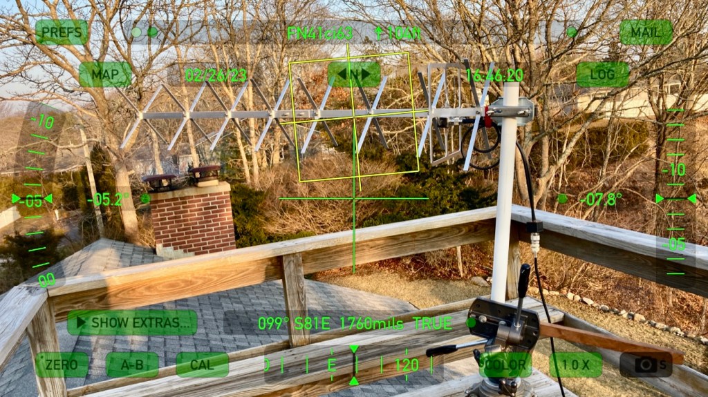
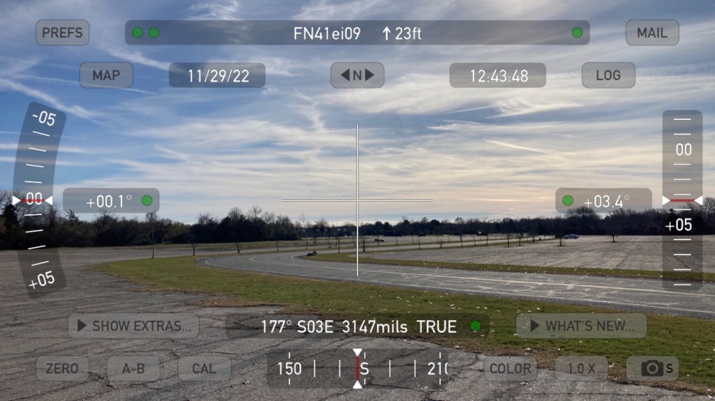
    • Start with more passes and then find better passes: When looking for an operating location, start by finding a convenient spot to where you live/work and try that first. An easy location with just-ok horizon can be an excellent spot to build technique. I use an app like Theodolite to document the cardinal directions and the height of the horizon due to obstructions. Make a little map, maybe. You can now use that to decide whether a pass will be worth setting up for. Or find a pass on the edge and see what you can hear and how well you can hit the satellite (or hear yourself).
    • Satellites Helping Satellites: Use a tool like Google Earth to scout locations with a clear horizon, especially to the east or west. Piggybacking on the previous item, I have found some excellent spots precisely because I needed to work a low-elevation pass to work a station in Europe or on the West Coast of the US. GE has Street View, and the line tool generates a terrain profile. Draw a line from your spot to the direction you want to work and see what it looks like. You can also drop to ground level and see the estimated horizon. It’s usually very close. I use Google Earth (or other mapping if you want) to scan for good locations.
    • Refine your portable locations: I have fine tuned one of my Greencube/IO-117 operating locations for Northwest-AOS passes this way and have a good number of JA stations to show for it. Here is the Google Earth Screenshot:

    Both of these lines show a 320-degree bearing at Ninigret Park in Charlestown, Rhode Island FN41ei. The line from Location 1 has a radio tower right on the 320-deg bearing, and some higher/closer trees. I used GE to find Location 2, where 320-deg is on the right side of some trees, but there are fewer obstructions, the radio tower is comfortable off to the north, and the trees are further/lower. This small change of just a few hundred yards got me into IO-117 earlier/lower in the pass and allowed me to contact more JA stations on these passes starting between 220-230 degrees AOS and running overhead to south-east to about 160-degrees at LOS.

    • All Is Not Equal: The correlation between how loud you are hearing yourself on the downlink and how loud the other station is hearing you on the downlink is “loose”. I often hear myself at true 59 on RS-44 and the other stations is not able to copy me. That could be polarization and antenna selection, the location of the other station, receiver type, preamps… That situation works both ways. A weak station might be hearing you very well while you can barely hear yourself. Just try to make the QSO. I record my passes and have exchanged recordings. It is interesting to hear what the other station is hearing.
    • Make skeds! I’ve been able to help other ops get closer to WAS because they needed Rhode Island, or FN41. It doesn’t seem rare but I have had plenty of European ops interested/scheduled. This little state has plenty of hams but not many on the sats. I went a long time with only one contact in FN41 and it took me a while to get it confirmed! Likewise, look for operators or rovers in grids and states you need. Many grids are only available this way as they have no resident operators.
    • Keeping track of uplink and downlink pairs: I have a document in a notes app on my phone with just the basic transponder info and it is very handy. If you use a downlink radio with a waterfall display you can get away with only keeping a note of the uplink and downlink center frequencies, transponder bandwidth, inverting/not, and doppler shift direction. You will use the waterfall to spot yourself, and if you correct manually for doppler you will be only tracking the 70cm radio most of the time. I use GoSatWatch or one of the other iOS apps for tracking passes, so having a transponder reference document on my phone is super helpful.
    • Keep an open mind about everything: I would like to finish this list with a shout out to Dragan, 4O4A, who tweeted this super helpful doppler correction procedure. Knowing the upper and lower limits of the uplink and downlink, plus the doppler offsets, is all you need. My mind is still a bit blown, but it is changing how I will approach the previous tip. For 2023 I will be making a passband-edge and offset document for the linear sats I like to work.

    How I approach a typical pass, and some other considerations:

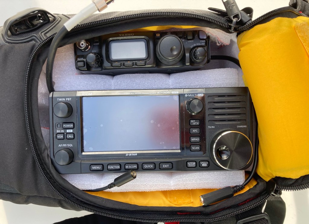
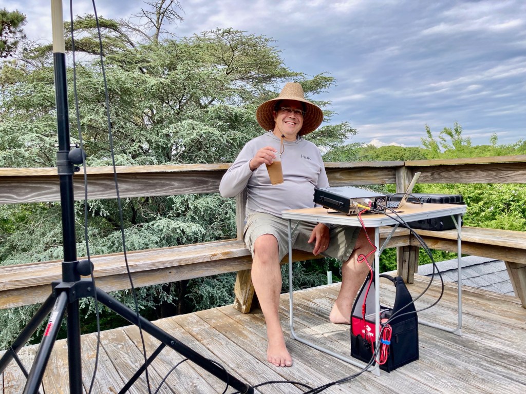
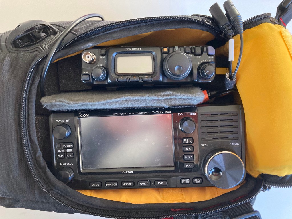
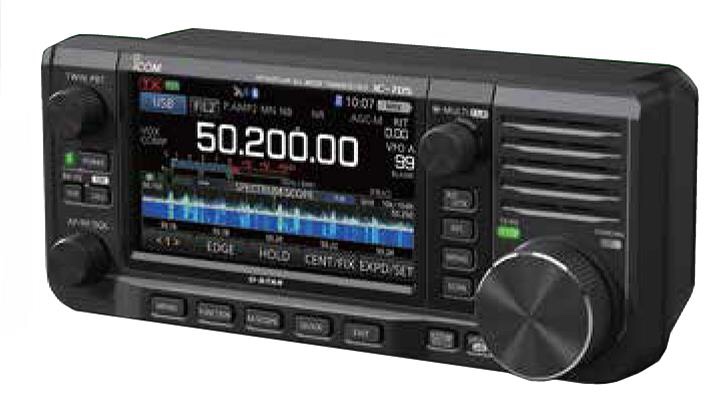
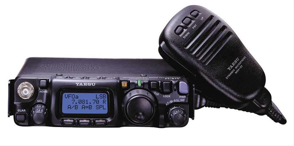
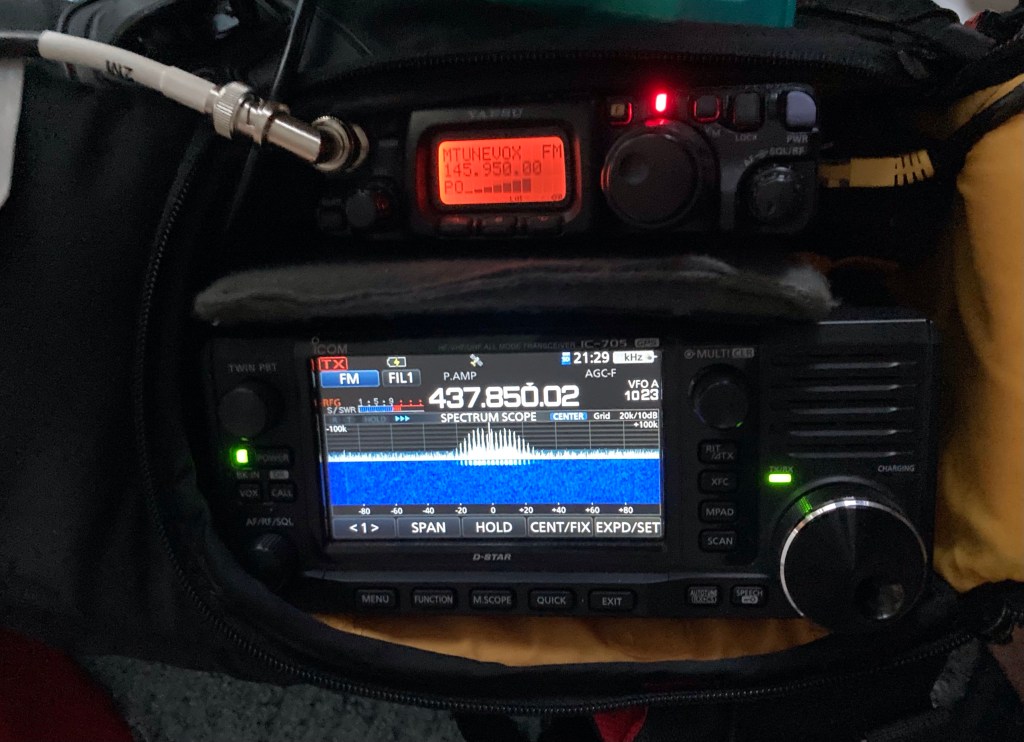
    Take RS-44, an inverting V/U satellite with decreasing doppler tracking, for example: My uplink is a Yaesu FT-817ND, set to 2M LSB, and I run it in VOX mode with a headset. My downlink is an Icom IC-705, in 70cm USB mode, and the waterfall set at 50KHz wide. I have a pretty good idea of UL/DL frequencies at or near AOS. Once I hear the bird well enough I will whistle and look for my signal on the waterfall. When I find it I move my DL frequency to a quiet section and move my uplink to match. That’s a good place to start calling CQ. I also might start by listening to the frequencies I “see” on the IC-705 waterfall. It gives me a quick idea of who is active and who they might be working. At that point I can call one of those stations, or move to a quiet spot to call CQ. I might do that several times over 5-10 minutes. I might make three or four CW calls, then scan the stations again.

    When I need to QSY I know my TX has to move the same amount (in reverse) as my change in downlink frequency (and v-v). If I move my receive frequency from 435.650 to .655 I have to move my uplink down (inverting) by 5KHz.

    On an overhead pass it is important to remember it’s a low elevation pass for someone. In my area that can be the Rockies and upper Midwest USA, through central Canada, or could also be Mexico and Central America. It’s easier for me to work those stations on a pass with a 35-50 degree W or S max elevation, especially since my home has a bad western view.

    So that’s what I have found useful as I started operating more satellite passes, and putting time into optimizing my routine. Drop a comment or an email if you find this useful, or have something to add. Best 73 and see you on the birds, Pete N1QDQ

  • Quick Greencube Activation Video

    Quick Greencube Activation Video

    I’m new to Satellite operations having started just over five months ago, but I’m not new to portable operations. I don’t build fancy rover rigs. I just secure my gear, use a good portable antenna support, and keep things “fast and light”. That means I don’t have much for rainproofing and am turning antennas by hand, but I like the flexibility.

    Here’s a short video I took at a portable IO-117/Greencube activation here in southern Rhode Island. The location is Ninigret Park, a former military air base and bombing target (!!!!). This video is from one of the large parking lots with decent horizon views. I am able to work passes down to about 5-degrees.

    A few additional items to fill in the gaps:

    I think the WIMO X-Quad is a good antenna. In use I have not found a way to get fade-free performance on Greencube. The RHCP harness works, but isn’t consistent. I have also run it by only feeding the Horizontal or Vertical inputs. Even though WIMO says it can’t be used like this, it can. I find it covers better with less fading, but when it goes bad it is just as bad as the RHCP setup.

    DC power is a 20Ah Bioenno LiFePO4. It will run this station at 25W for multiple passes. Probably 6 or more. I don’t transmit too much so it is mainly the 1-Amp idle current of the 991A that eats up capacity.

    I buy Times Microwave LMR240-UF (Ultraflex) in bulk and build cables as needed. I like the DX-Engineering crimp/solder PL-259s for 8X/240, and they sell good BNCs at a variety of price points. I wish the flex was a little more “ultra” but the performance at UHF is worth some stiff handling.

    I’ll be sure to make another video when I have a windproof mic and I’ll go into more detail.

    Enjoy! 73 N1QDQ

  • Greencube and You (meaning me)

    Greencube and You (meaning me)

    One thing that long-time satellite ops will tell you is they worked birds that are long out of service, and they had some amazing capabilities. While we can’t bring them back we can try to take full advantage of the sats we have while we have them. Here in the northeastern USA we don’t have many nearby DXCCs. FO-29 and RS-44 are reliable LEOs that put some of Europe in a common footprint with my station, but the limitations are clear. I just don’t have access to many DXCCs from FN41. When I started my path toward working satellites in early 2022 I realized we didn’t have a Mid-Earth Orbit (MEO) or Geostationary (GEO) like QO-100 accessible to North America. So in early 2023, when I heard we might have a MEO bird available to hams, I was very interested.

    The newest and highly popular kid on the block is Greencube, aka IO-117, a Mid-Earth Orbit (MEO) satellite with a 435MHz digipeater on board. This is good news because the footprint is huge, allowing access to grids you won’t get on RS-44 or FO-29, as well as Zones and DXCC Entities you won’t get any other way. I am still not in a great spot for those European DXCCs, but I have worked plenty of them now, along with stations in Africa, Japan and China, so it’s working well enough.

    One good thing about IO-117 is you do not need a full-duplex radio to communicate with it. It’s a simplex digipeater much like the ARISS FM APRS digipeater. You do need some way to track uplink and downlink doppler independently and this is typically done in split mode. My Yaesu FT-991A is a very good choice for this application. It can put out 50W max on 435Mhz and split mode is no problem as it is a dual-VFO radio.

    THE BIG DISCLAIMER: None of the other tutorial pages for this kind of thing worked for me as written. Mine will probably not work for you as written. You will need to know how to configure audio and CAT devices. Your base frequency for doppler correction might be different. Your CAT software might handle doppler correction differently… You should be familiar with the software packages you are using. Be ready to crack a manual. That sort of thing.

    Here’s a blow by blow of how I got my Yaesu FT-991A to play nice with the software needed to access IO-117.

    The Elements of my IO-117 Station:

    • Yaesu FT-991A
    • Windows Laptop
    • USB Cable w Ferrite Chokes
    • Ham Radio Deluxe software
    • UZ7HO Software Modem for Greencube
    • UZ7HO CAT.dll file in directory with Soundmodem
    • OZ9AAR Greencube Termimal
    • Eterlogic Virtual Serial Ports Emulator

    The challenge for me is to get my computer to track the uplink and downlink doppler corrections over CAT, while also allowing UZ7HO Soundmodem to access the PTT over that same same CAT port. The VSPE software takes care of that.

    What you will definitely need is a good IO-117 entry for your Doppler.sqf file, or a good base frequency for doppler correction. That will tell the software what kind of correction to make and what the rig is expecting. Check HF5L’s FT991 tutorial for more info, but this entry is a good starting point:

    IO-117,435308.7,435308.7,DATA-USB,DATA-USB,NOR,0,0

    My base frequency is around 435.308.7Mhz. You want to adjust this base frequency until the IO-117 downlink signal is centered at 1500Hz in the Soundmodem waterfall. It doesn’t have to be exact, but it has to be close.

    In order, my startup routine is:

    • 991A connected and Ports noted in Device Manager
    • 991A in Split Mode
    • Set up VSPE as Splitter
      • Yaesu Standard COM Port to an Unused Virtual COM Port Number
    • Open HRD
    • Connect to Virtual Port
    • Open HRD Satellite Module
    • Select IO-117 pass in HRD Satellite
    • Open Radio Control, Check Both RX and TX
    • Open Soundmodem
    • Open GC Terminal
    • Open GC Telemetry (be sure to check TCP Client box)

    Here’s the VSPE setup. The VSPE Device you want is a Splitter:

    My Yaesu Standard COM Port is COM6, and I am choosing COM20 as the Virtual Port. All your apps will now address COM20 with no sharing issues. TIP: Once your configuration works use the SAVE function and put the config file in with your other Greencube stuff. When you start a session just OPEN the saved config file, and Bob, as they say, is your uncle.

    At this point the radio should be tracking Doppler shift in both VFOs. Remember that the RX Freq is Plus Doppler Correction and the TX is Freq Minus Doppler Correction. Once the satellite passes the point where the shift is Zero, the sign of the Doppler shift correction changes to negative so you will see RX decreasing and TX increasing. That’s normal.

    The Soundmodem and Terminal setup can be a challenge if you aren’t familiar with these packages. I’m not doing a UZ7HO guide, but the communications part goes something like this:

    • Open UZ7HO for Greencube
    • Make sure you have the Audio Ports set correctly
    • Set CAT to Virtual COM port, Select rig, baud, RTS/DTS…
    • Once you have audio and have confirmed PTT operation…
    • Open Greencube Terminal

    I don’t have a al-az rotator for my antenna so I manually point it at the sat. That’s not a big deal because you don’t have to be too fine, and the apparent motion of the satellite is not too fast. I make maybe seven or eight corrections over the course of 45-60 minutes. Yes, a typical pass lasts an hour or more. Welcome to MEO. It isn’t like frantically chasing CAS-10 across the sky!

    I’ll go into the antenna side in a bit, but if you are pointing anywhere near the bird you should hear packets and see something on the Soundmodem waterfall. You want to see the GC downlink signal centered arond 1500hz and the decode “bar” in the waterfall set the same way. You can change your reference frequency in HRD Satellite and see the change in real time. I wouldn’t lean too hard on moving the deode bar or picking a different center frequency. These settings might get you some downlink decodes, but it will mess up your uplink frequency.

    At this point you are ready make contacts. There is more on this below, but my advice is to be patient. There are many stations transmitting packets at the satellite. Just try to transmit between downlink transmissions and you will get digipeated eventually. There is a pattern and you will get the hang of it pretty quickly.

    Helpful Links:

    Greencube Observer – Put in your grid and see which stations are in your possible footprint

    FG8OJ Greencube Setup – A comprehensive page about IO-117 from Bert FG8OJ, one of the early GC ops

    UZ7HO Main Page – You will get a security warning, it’s not HTTPS, but you want greentnc.zip and ptt-dll.zip

    OZ9AAR Greencube Terminal – The Cadillac of GC Terminals. Use this one. You won’t be sorry.

    DK3WN Telemetry Software – A telemetry decoder application. Useful!

    Antenna Chat:

    I’m using a 70cm Wimo X-Quad on a heavy Gitzo photo tripod. It isn’t fancy, and it isn’t automated, but it works. I use the very fine iOS app THEODOLITE to set both azimuth and altitude. Until I have the mone-ays (sp. Monet) for an automated alt-az setup it is all armstrong rotation for me.

    During the pass I use GoSatWatch on iOS (Sky Mode) to know where the bird is, and Theodolite for iOS for setting the azimuth and altitude of the antenna.

    WIMO X-Quad

    The X-Quad has parallel horizontal and vertical inputs, and they make a phasing harness for circular polarization. In my naivete I thought RHCP was going to be a set-and-forget decision. That has not been the case. In fact, I am often connecting straight to the horizontal input and that seems to have less fading and better performance. That kinda means I could have bought a yagi with better performance, but the X-Quad is a steal at under $200 and it fits in the back seat of my car. So I’m happy with it and would buy it again.

    The X-Quad has a good published pattern but it isn’t so tight that I am chasing the sat around. I typically move the antenna aim-point in 10-degree increments, putting the antenna 5 degrees ahead of the bird, letting the sat cross the antenna’s capture area. In many cases you can widen that out to 15 or even 20 degrees with the antenna 10 degrees ahead.

    Predicting IO-117 Passes:

    Use your choice of satellite pass prediction application and get used to the times and types of passes you have at your location. For me it is the usual East, Overhead, and West passes, but the western passes appear to cross NW-NE, as opposed to a SW-NW pass like RS-44. This is a good thing as I can often work the last third of that pass down to about 10-degrees toward Europe and Asia. YMMV, but when you put in the time to examine pass orientation and satellite footprint you will make more and further contacts.

    SATPC32 is still one of the best apps for analyzing passes in non-real-time. You can plug in a time/date and an interval and see what the footprint will cover during a pass. On Greencube it can be a little disorienting because the footprint is so huge, but it can help plan your operations if you are interested in contacts at the fringes of the coverage. And, trust me, you are.

    Here’s a short discussion of IO-117 operating practices:

    If you have worked, or more likely attempted to work, the ARISS APRS digipeater then you have an idea of what IO-117 is doing. It is listening, decoding incoming packetized messages, and then retransmitting them, all on the same frequency. Much like FM sats you are essentially fighting capture effect. The strongest stations have the best chance of being digipeated when there are many stations transmitting. You can’t work around that. You will notice a pattern of digipeats, telemetry packets, and gaps where the digipeater is listening. Find your own approach to getting heard.

    A good example of where digipeater operating practices fail is when you show up as a new station, or another new station shows up, it becomes a frenzy of QSO requests. If you are the “DX” I suggest just relaxing and working one at a time. It will be difficult because stations will keep calling you even if you are in QSO. It will suck as you try to get digipeated while doing whatever else you need to do (like pointing an antenna or even tuning a VFO). It is frustrating and you probably work half the stations you could (that’s optimistic) because those same stations are clogging up the digipeater even though they have clearly been digipeated several times and everyone knows they are there. Take that knowledge with you when you see a new station. All those “me me me” calls are just making it harder for the DX to make the contacts they are hoping for.

    Therefore…

    Here’s a short rant regarding IO-117 operating practices:

    IO-117 is a flying digipeater, and as such it has very limited bandwidth when it comes to messaging. If you see 20 stations on a pass, most of them are trying to get digipeated. Only one or two will get digipeated on each transmission because Greencube is only digipeating the transmissions it can decode. As well, there is no time synchronization so it is receiving a morass of signals. My rule is to transmit as little as possible, and only CQ when absolutely necessary. This approach reduces the QRM the digipeater has to deal with.

    However… There are operators who will send a CQ message every 60 seconds, or even more often. This is simultaneously bizarre, counterproductive, and boorish. If you have worked a FM bird like the ARISS FM Voice Repeater you know this pattern. You hear two stations trying to complete a QSO and another op calls CQ. They can hear that station trying to get a grid confirmed (usually because someone doubled over that station), but they don’t care. A digipeater has the same limitations, and the same bad operating practices. Rise Above.

    I have worked a lot of VHF contests and thrown my call around in many DX pileups. As hectic as those situations can be, most stations will back off to let the DX complete a QSO. Not so on Greencube. Everyone just keep calling and calling, unwilling or unable to realize the reason the DX isn’t working ANYONE is they keep “winning” on the uplink, and the DX keeps losing.

    As for the ultra-frequent CQ calls it is obviously a way to avoid having to compete in a pileup if a new station appears. The hope is the new station will call the CQ they see before just calling a station they see in QSO. As above, they are taking up digipeater slots that the “DX” needs to get digipeated themselves. Four big-gun stations sending CQ every 60 seconds are monopolizing about a third of the available slots in any given minute. Probably more.

    Here’s an actual screengrab from a IO-117 pass. If a weaker station was trying to get digipeated they will have given up at some point.

    That’s an extreme example during a quiet pass over South America. But you will see this during crowded conditions.

    Rant Mode Off, but I hope it helps at least frame the issue of a limited resource and how easily it can be wasted by bad operating practices. Enjoy, and Best 73. N1QDQ

  • 2022 News Flash – Yaesu FT-818ND Discontinued

    2022 News Flash – Yaesu FT-818ND Discontinued

    The Golden Retriever of the Amateur Radio World

    As 2022 draws to a close the amateur radio community was in a bit of shock as Yaesu announced that production of the FT-818ND will cease as well as the FTM-400XDE.

    Greater minds than mine have paid homage to a classic:

    K4SWL at QRPer.com

    OH8STN recounts his feelings here

    A thread on the SOTA.uk board

    And EI7GL pays tribute

    On one hand it is sad because the FT-817/818ND has been and still is such a great radio for so many hams. I had owned three of them (maybe four) before buying a used 817ND in October as a portable LEO uplink radio. I now own a second one which I will not be parting with any time soon. I “speak Yaesu” having owned many Yaesu radios, and currently own two 817NDs, a FT-991A, a FTM-300D, and a FT3D. (I don’t have a problem, YOU have a problem!)

    The 817/818’s low price, wide RX and TX coverage, and small size have made it the right rig for many purposes. The paired 817/818 (1634/1636) approach put thousands and thousands of QSOs in the logs of satellite ops. It has also been a mainstay in backpack/SOTA/POTA operations. They are found as IF rigs in many microwave stations. Even with the original battery it is one heck of a self-contained QRP radio. With one of the modern high capacity replacements it is even better. It is a natural for manpack operation with that front-mounted antenna connector. The one I recently purchased was in use as a bedside radio checking 80M and 40M net activity for a long time ham! It’s the Zelig of Amateur Radio.

    They are known for durability, with some claiming they will be the cockroach of the used amateur transceiver market. They have an alloy chassis, metal covers, and a simple and not-fragile control/display cluster. The aftermarket has been very good to the 817/818, with all sorts of mounting, power, antenna, and user-comfort accessories available. A blind spot in the aftermarket is a reliable source of crystal filters. That would be a game changer. One of the rigs I owned about 15 years ago had both of them installed. Before the supply dried up. Kicking myself but that’s how it goes.

    On the other hand this was predictable. Was it a perfect radio? Not even close. At its time of release it was known that the internal battery was garbage, the idle current was high, the power connector was terrible, the receiver was average (though not fatiguing) and it kinda needed those expensive optional crystal filters to be really useful, especially on CW. Oh, and the original FT-817 had an appetite for final output transistors. Even though the design and construction are more expensive now than they were 20 years ago the price has remained very stable. That’s not sustainable. The boards are full of discrete components, not offloading a lot of features onto a big CPU like you see on the Icom IC-705. It is a throwback radio in a world of muscled-up iPhones with an antenna connector.

    I’ve written in this blog that I believe Yaesu is philosophically incapable of making a real competitor to the ICOM IC-705. They have doubled down so hard on HF+6 contest/DX radios and have gone so far away from the 817-type market that I don’t see them coming back. The 705 could be described as a 10W IC-7300 and a 10W ID-5100 shoehorned into a small box with a big display. It also uses a standard Icom battery. Brilliant. There really is no equivalent in Yaesu-world. Maybe a FTdx10 and FTM-300 mashup? Maybe I’ve just been juked too many times recently by Yaesu’s teasing of a groundbreaking new radio only for it to turn out to be the FTdx10, or the FT-710. The latter was especially tough because that was the rig I thought would be the IC-705 competitor and I could not have been more wrong.

    I feel lucky to say that I run a 817ND and a 705 side by side in my LEO-bag rig, and it is an amazing contrast. I’d take the 705 receiver and DSP all day long, same for the built in recorder and the ICOM twin filter, but the simplicity of the 817ND and the flexibility, especially the dual antenna connectors, is unmatched in a shack-in-the-box rig. Once the noise dies down and the price gougers get their fill we can expect a long post-production lifespan fot these radios. Not unlike the ICOM IC-706/MKII a rig this capable will always be attractive.

    Here’s to the little rig that could, and can, and will. Cheers.

  • Papa’s Got a Recycled LEO-Bag! It’s In The Bag – Part 2

    Papa’s Got a Recycled LEO-Bag! It’s In The Bag – Part 2

    No apologies to the godfather of soul, James Brown! Maybe my favorite JB quote is about “show business”, and I paraphrase: It isn’t Show Business, Its Show, and Business!

    So, on with the show…

    When it comes to portable full-duplex stations for linear LEO satellites there are plenty of examples to show you the way. In some form it involves two radios held together in some fashion, and positioned so the operator can manipulate both during a satellite pass. A pair of Yaesu 817/818 radios is the standard rig. You can find them used for under $500 each, and they are very well supported by the aftermarket industry. There are several options for mounting rails that hold both radios in position and make a very solid platform. You can use this setup “naked” hung around your neck on a strap, or slide the setup into a bag that can hold an external battery pack and give the whole shebang more protection from [gestures in all directions].

    KB8BMY Living Dangerously

    In my case I already owned a Icom IC-705 which I have already crowned the modern classic that changed how we look at amateur radio transceivers and what features we expect. I used it for my first satellite contacts which were a tragicomedic lashup of the 705, a Yaesu FT-991A, an antenna on a tripod, a hand mic, headphones… The crazy part is I have a Heil Pro 6 headset! I was so wrapped around the axle and nervous I didn’t think to use it. That was not a portable setup. It was the opposite of portable. The fact that I made a few contacts on it is a minor miracle, but it did set the hook!

    The next step was to find a suitable radio to pair with the IC-705, and the best solution IMO is the FT-817/818. I found a used FT-817ND for about $425 and started looking for a suitable bag to mount them in. I have a few camera bags on hand, and one of them is this KATA 3IN1-20 (discontinued) which was a total fail as a camera bag. The dividers were crap, the top compartment is weird, none of my gear fit in it, but I kept it because it was cheap and I’m a bit of a gear squirrel. These can be found used, and Manfrotto also sold a re-branded version with the same model number. It’s a backpack, but I use it as a sling-bag and it works great like that.

    My first attempt to mount the two radios in this bag (see my previous posts for photos) involved some spare camera bag dividers and a bunch of pluck-apart foam. I just sectioned the foam into blocks and use it to support the radios. It was a cheap way to get a useful result without committing to expensive and time-consuming construction. It worked. The bag is not ideal, but it’s as close as I need it to be. The foam had a bit of give which was both good and bad, depending on whether I wanted stability, or the ability to dig my hand into the bag to deal with a loose connection (probably from the slop in the soft foam support).

    I started thinking of other materials that could work. Foam-Core and corrugated plastic “coroplast” panels were one idea but I didn’t think the rigidity would be a good match for the soft bag. While doing a winter garage cleanout I came across some big blocks of PE foam from a bicycle packing box. That stuff is a good compromise between rigidity and “give”. It is often a laminated material formed into blocks from 1/8″ sheets, or solid blocks, which are often assembled into other shapes, or cut to form-fit an application. Places like ULine carry it, and I am sure you can get it cheaper elsewhere.

    This material cuts beautifully with a large razor knife at full extension. Any long, sharp, thin blade would be good. If you have the laminated material you can often separate it at a seam with with your hands and maybe a little cutting.

    Then came the issue of bonding. I saw a few YouTube videos and one of them compared contact cement and hot glue. Hot glue looked like a good option.

    I include a link this video so you can avoid it:

    Tragic PE Foam Video

    IT IS NOT A GOOD OPTION!!! It makes a mess and you will be sorry you tried it. I am a bit of a grinder so I stuck with it and use it for my whole build. Don’t be me. Both contact cement and hot glue are bad options compared to hot-air bonding. You have a hot air gun for things like heat-shrink tubing? Good. Use that. Don’t have one? Get the cheapest gun that doesn’t fall apart when you look at it wrong, like the Harbor Freight gun, and use that.

    Here’s another great thing about the heat gun approach. It’s great for cleaning up cut edges, any ratty sections where you had to separate or had a mistake cut, and turning a rough edge into a nice smooth one. If you get too enthusiastic you will melt through it, but blowing hot air over the surface and maybe smoothing it out with a finger is a nice way to get a cleaner finished result.

    BUILD THE DAM THING ALREADY!!!

    Now, on to some photos of my actual build! You knew we would get to it eventually. Thanks for hanging in there. Treat yourself to a healthy snack or just stress-eat a sleeve of graham crackers chased with a Frappuchino. Whatever. You’re great.

    My Kata 3in1-20 Camera Bag

    With both a radios mounted in the bag you can see how they sit in a good position. They are low enough to be protected when I close the flap, but I can still access them easily. There are a few issues. One is the IC-705 tuning dial is a little close to the flap. Another is the access to the FT-817ND front antenna connector. Also the power button on the 817 can be a little tricky. I can solve most of this by using a thinner diving panel between the radios and shifting the 705 a little to the left. I built a short jumper from LMR-240UF to get the IC-705 antenna connection into a better spot. It’s much better (not a loss magnet and SWR burglar) than those BNC Right Angle adapters. I connect the uplink coax directly to the 718ND.

    You can see how the compartment extends under the Cordura on the left, so there is about 2″ of foam over there. The main compartment zippers almost completely open so I was able to insert it without bending the heck out of it.

    Radios Mounted in the Bag

    To build the foam support I just made a measure of the interior dimensions of the compartment, then positioned the radios, and mocked up PE foam blocks to get the radios to the correct height and spacing. Once I was happy with that I got to work with the hot glue (tragic, but it worked). The details are a channel for the IC-705 power cable, access to the 817’s power connector, and a recess to neaten

    up the wiring harness.

    Top View of the Foam Monstrosity
    Bottom View with Harness

    On the 705 I use that BNC extension for the antenna and a short headphone extension with a right angle male to straight female connector. The mic connector I use is an Inrad Yaesu Modular Adapter, or a Yaesu AD-1-YM.

    Business Side of the 705

    My power supply is a homebrew 8Ah LiFePO4 battery. I built it a few years ago following the OH6STN build video. It’s four Headway “Tesla Cells” in a 4S configuration with a 30A BMS. It fits cleanly in the top compartment of the bag and I can pass the power cable and connector through the zippered divider. Yes, this bag is full of zippers!

    LiFePO4 Battery
    Power Cable to bottom of main compartment

    One of the best purchases I made for my power needs is a Bioenno BPC-1503CAR DC-DC charger. I snipped the automotive “cigarette lighter” plug and put Anderson Powerpoles on it, and I use it to maintain my two LiFePO4 batteries. I put a distribution block in the power harness so I can charge without disconnecting the radios, or power an accessory without needed to modify the harness.

    Bioenno BPC-1503CAR charger in action. It will deliver 3A max during charging. I’ve used it mobile in my VHF Rover setup.

    So that’s how it all came together. I will probably build another insert but for now it is getting the job done. Here’s a shot of the rig while I am operating.

    FPV! (just after a pass when I was shutting off the 705’s recorder)

    My home has this odd feature of a rooftop deck! Here’s a bonus of a deck image showing my little window to the northeast, allowing me to work some of those low RS-44 passes toward Europe. RF Noise can be an issue (Solar inverters, lights, houses…) so even though my horizon is only about 2-degrees it is not the best spot. But it’s super convenient and I can be QRV in just a minute or two.

    View from the Crow’s Nest

    I hope this has been helpful, and maybe edutational! If you have questions or comments you can leave them in the comments or drop me an email.

    73 and See You On The Birds!

  • LEO Learning Curve

    LEO Learning Curve

    Note: I got caught by COVID and am isolating, so now I’m getting caught up on blogging. Also focusing on keeping my wife safe and healthy while I get through this. It sux. No fun. I’m off the sats for a while while I recover. On with the blog.

    Recap: My setup is a Yaesu FT-817ND and an IC-705 mounted in a backpack/sling-bag. The power source is a 8ah homebrew LiFePO4 battery. It isn’t especially lightweight but it is feature-rick thanks to the IC-705. In my setup the 817 is always the uplink rig. The 705 is always the downlink rig. All I do is switch coax connections when switching from U/V to V/U mode. I am 100% portable with no fixed antenna setup. That applies to all my amateur radio activities. I’m using my experience in VHF Rover contesting, hilltopping, portable QRP HF, and everything else to get up to speed on linear satellites.

    I made my first QSO on a linear satellite in late October of 2022. I have had my fair share of learning experiences, setbacks, exciting contacts, and I learned a few things. Here’s a rundown of what issues I ran into, and how I resolved them.

    Interference Issue: The immediate concern when I put the rigs together was the amount of noise the 705 was picking up on 70cm when transmitting on 2M with the 817. The 3rd harmonic of 145.960MHz is 437.880MHz. The 705 was receiving a big signal on 437.880, and it was crashing the front end of the 705. Normally the spur is not that big. This interference was preventing me from hearing the downlink when transmitting. Not a good place to be. Also, it is common to install a 2M low-pass filter to knock down any harmonics. Even with that It wasn’t helping. One reason for excessive spurs is an improperly biased or over-driven stage in the power chain. I finally bit the bullet and decided to re-set the bias on the 817’s power section. That’s an easy procedure than can be done with an ammeter. It made a huge difference. I’ll be adding a high-pass filter on the 70cm side, but for now the solution is good enough.

    FT-817ND transmitting on 2M, 3rd harmonic received on the IC-705

    Cable and connector choice: Aiming a handheld yagi at a briefcase-sized box hurtling through space is hard enough. You don’t want to make it harder. I make my own cable assemblies and usually have bulk cable on hand, along with connectors. My first set of cables was RG-8X with some decent BNC connectors. I was also using a right-angle Male/Female BNC adapter on the 817 and a coax jumper on the 705. My concern was minimizing stress on the radio connectors. The 705 has a BNC-F antenna connection on the side, and I didn’t want to run the coax through the shoulder bag.

    While I was debugging the spur issue I stumbled over a high SWR issue. When I thought the 817 was in PWR-meter mode it was actually in SWR-meter mode, and it was showing high SWR. I made a simple SWR analysis of my cable runs using the SWR-meter mode on the 817, and did the same with my cross-needle SWR meter. The results were clear: BNC adapters can be a problem, especially at 70cm, Coax types like RG-58 and RG-8X are not great choices for this application, and I may have been having a high-SWR problem along with other issues causing my interference problem.

    In 2021 I switched to Times Microwave LMR-240-UF (UltraFlex) for my VHF/UHF Rover setup, so I have plenty of it in bulk, and some good connectors. I built new 6-foot (2M) jumpers and ran them as directly as possible to the radios. For the 705 I built a short LMR jumper with BNC-right-angle on one end and BNC-F on the other, just long enough to get the connection above the radio. LMR-240-UF has low loss figures (much better than “HF” grade coax) and the cable has a foil shield between the braid and the dielectric; providing better shielding and less noise. It isn’t quite as flexible as other coax cables. I looked at Messi & Paoloni Hyperflex 5, which looks lighter, more flexible, and has great loss numbers. I’m not crazy about the connector selection, but it isn’t the worst. They have a BNCs in straight and right-angle.

    Operating Locations: SO far I have mostly dealt with equipment, but what really makes a successful satellite pass is location. Having a good view to the horizon is essential for working low-elevation passes, and those passes are where the DX is. In VHF contesting I was primarily concerned with elevation. Height is might when choosing rover locations. And while a high location with panoramic views would be great but I live in coastal Rhode Island where there are few of those. What we do have is water, and a view over water is often good enough. I have found a few spots, though I am on a south-facing coast where views to the north, northeast, and northwest can be hard to come by. There are many tools you can use to scout locations. I have been using Google Earth for a long time. It shows elevation under the cursor, and has an elevation profiling tool as part of the line tool. HeyWhatsThat is another good tool for elevation profiles, I just haven’t figured out how to use it very well (yet).

    Funny Story! I often operate from Ninigret Park (within Ninigret National Wildlife Refuge) in Charlestown, RI which has a history as a naval air station, training field, and a bombing practice target. I use the GoSatWatch app for tracking passes and it usually does a good job in Sky View of showing the track of the bird and it will use the Apple compass to orient itself. Unless there is a unknown amount of ferrous metal under the parking lot! In an area I had chosen for it’s northeast view both GoSatWatch and Theodolite cant get a bearing fix, and it will swing wildly as I walk around. Aliens. I’m sure of it. But either way use mapping to get an idea of cardinal directions at your location because aliens could be throwing your fancy digital compass for a loop.

    View to the South at Ninigret NWR

    Another consideration is QRM/RFI. I had been using a parking area near the beach for because it was easy and had decent horizons. There was noise but I could work around it, until one day when the RFI was overwhelming. That was the first time I operated from there during the day. The noise was solar-panel inverter hash*. So that’s another consideration. Pointing a directional antenna at a residential area means you might be getting some of that junk in your receiver.

    My home QTH isn’t all that bad for working satellites, especially now that the leaves are off the trees. Back we were looking for a home in coastal Rhode Island the realtor was showing us a variety of properties. Along with her choices, I was using Zillow to run searches and see what the market was like. One house kept popping up but the pictures were not great and I couldn’t tell what it really was… and is that a deck ON THE ROOF?

    2022 June VHF on the Roof

    The answer is yes, it has a deck on the roof. It makes for a nice spot to have a cup of coffee, do a crossword, freak out the neighbors, and mount antennas. My shack is 100% portable so I often mount a J-Pole, or my “armstrong” VHF stack, up there. It’s also where I set up my 991A/705 for my first linear sat contacts. I don’t have good sight-lines to the horizon, except to the SSE, but it is better than nothing. I do have a clear section to the northeast where I can work passes in the 8 to 10 degree and higher range. And if I have to work through the trees I will still make contacts, just not as many. This has been great for learning my way around the birds, working new grids, and I have even made some good contacts into Europe, Mexico, and the US West Coast from here. I can be QRV in a few minutes and it has been a great way to get on the air even if I don’t have a lot of time to spend.

    A Wrap-up with some Tips:

    Be patient while debugging problems in your system

    Use the best cable and connectors you can manage

    Whatever location you have access to is fine. Keep looking for good spots.

    Whatever radio you have is good enough to get started. A few posts back I was building an Eggbeater Antenna for 2M because I was trying to work the ISS Digipeater. There are good ways to work simplex. A pair of HTs is a good FM setup.

    I will always speak up for listening above transmitting. It is not easy to hold back on the PTT but there is a lot to learn by listening.

    For your first contacts on linear satellites, find yourself on the downlink, get into a clear spot, and call CQ. This is much easier than getting on frequency with a calling station when you are starting off. Let the other op help you out. Just like juggling, start with two balls before you move on to three.

    Since I don’t use any doppler-correction software I follow the “always tune the 70cm side” rule once I am on frequency. If I am on RS-44 I am tuning the 70cm downlink and keeping my 2m uplink fairly fixed. If I am on CAS-4B I am correcting the 70cm uplink and keeping the 2m downlink fixed.

    I’ll be back in action once I recover from this bout of the ‘VID. See you on the birds. 73

    *The worst part about this problem is that the remedy is cheap and easy. Chokes on the supply and distribution lines have been shown to be effective as the noise is radiated along the wiring. I was looking into solar panels for my home and asked the rep about RFI reduction and got a blank stare. It’s troubling how these devices are being deployed with no regard to their broadband RF emissions.

  • Full Duplex Satellite, It’s in the Bag – Part 1

    Full Duplex Satellite, It’s in the Bag – Part 1

    Opening Salvo directed at amateur radio transceiver manufacturers: The lack of affordable full-duplex all-mode radios is why I have to write this. You would think the shack in a box (SIAB) market segment would have at least one or two full-duplex-capable radios. You would be wrong. Buying new? You can buy the Icom IC-9700 VHF/UHF All Mode, and that is pretty much the whole list. It’s a great radio but close to $2k USD when new, and $1500-1800 on the used market. It can be used in a portable station but the radio plus battery are on the heavy side. For a “hang it around your neck” portable station it is not a great choice. For everything else it is the modern standard for the V/U weak signal and satellite operator.

    Icom IC-9700

    Thankfully the world of QRP SIAB rigs provides an easy hack: Bolt two affordable Yaesu FT-817/818 radios together and you now have a dual-VFO all-mode 5-watt ground station for communicating through low-Earth-Orbit (LEO) satellites. That setup has proven to be effective on LEOs, and has put a lot of grids in the log for operators across the globe.

    A few years back I was looking at QRP radios and the Icom IC-705 had just come on the market. After some extensive gear-liquidation I bought one and it is a little miracle of a radio. It comes close to being a ham radio for the iPhone generation. It is everything the FT-817ND isn’t. It is feature-rich with a big display, easy menus, well placed controls, single-USB access to a built in audio card and two virtual serial ports. I have used it for field-portable operation, in my shack, mobile, and as an all purpose travel radio. It is a modern classic in the way their IC-706-series radios were 25 years ago.

    Icom IC-705

    I mostly use Yaesu gear but Yaesu doesn’t make anything like the 705. I’m not sure they are philosophically capable of making anything like it. They infamously countered the release of the 705 with the FT818ND, a mild FT-817ND update (6 Watts!!). It was the most Yaesu thing ever, further cementing their commitment to zagging when all anyone wanted was a zig. They also released a direct competitor to their own FTdx10 in 2022 with the FT-710. Anyone who was hoping for a FTdx10-like successor to the FT-991A (Raises Hand) was left kicking dirt and letting out a Shatner-worthy “Yaaaaaeeeeessssuuuuuuuu!!!!” over their clenched fist.

    I have to put in a strong word of support regarding the FT-817ND. On one. It is a brilliant little radio and the ham landscape would be much worse without it. I have owned one at least three times and it always punched above its weight. It is so small you can’t really grasp that it covers 160m through 70cm including general coverage shortwave, air band, and VHF utility. It’s not a museum piece.

    Yaesu FT817ND

    I know it isn’t a museum piece because I recently purchased another one to use as the uplink radio in my LEO setup. Firing one up again was like meeting an old friend. Those menus are simple and effective. The front and rear antenna connectors are a gift. The internal battery gets you half power, and there are now modern battery chemistry replacements delivering more voltage. The display is good enough. Yes, the VFO/MEM button sits right on top of the main dial. Same for the F/MENU button. You will QSY while using those buttons. You will forgive the radio.

    Meanwhile, here in the 21st century I like my IC-705 with the big waterfall display, cushy controls, and features like built in audio recording with frequency and time stamp data. That’s what I am using for my downlink radio. The waterfall makes it a breeze to find yourself on the downlink and spin the uplink VFO to get where I need to be. (Yes, the 817 can tune while in transmit on SSB. Not on FM. The more you know…) The Twin Bandpass Tuning is easy to adjust and can fight QRM from adjacent stations. The internal preamp is not a feedpoint-mounted LNA, but it does the job. You want that stuff. The 705 is fantastic downlink radio.

    First iteration of my portable satellite station

    My hybrid 817/705 station is just fine until I squirrel enough funds to get a second 705. Maybe it isn’t even necessary. The next blog post will examine the growing pains and issues I encountered while building his rig, but as we head in to December 2022 I have worked out the worst of the bugs.

  • CQ Satellite!

    CQ Satellite!

    RS-44

    I took the plunge into operating the amateur radio linear satellites a few weeks back and it has been a fantastic experience. My plan here on the blog is to share a few “blow by blow” accounts about what worked and what didn’t, what I have improved and how, and what’s next.

    Phase One – Get on The Air

    I’m a fan of “shack-in-a-box” radios so I already had the basic equipment necessary to operate on a linear-transponder LEO satellite. I used my Yaesu FT991A for the uplink, and my Icom IC705 on the downlink. Using the IC705 on receive made sense because the display on the IC705 is better, it has a built-in audio recorder, and it has options for things like bluetooth audio if I wanted wireless RX via earbuds, etc… I had to configure my station so I could manage two radios and point the antenna. I arranged the rigs so I could sit in front of them (I’m not hanging a 991A around my neck) and reach the tripod to point the antenna. I have a Heil Proset6 which I have used on the 991A so I had a wired solution for audio. I was not comfortable enough with the function of my internal “Profanity Suppression Module” (aka PSM) to use VOX, so I used the HEIL PTT trigger switch. This tied up my hands but I was mostly interested in tracking the satellite and finding the downlink.

    The antenna I use is an Arrow II, Initially I mounted it to a photo tripod so I could have some kind of sanity while I figured things out. It helped. I was able to track the bird and didn’t have much polarization-related fading. The Arrow is two antennas sharing a common boom, so there are two feedpoints. I purchased mine with the optional duplexer which turned out to be a good thing even if I am not using it as a duplexer. It can serve as a 2M Low-Pass Filter for 2M uplink, or a 70cm high pass filer, by only using half of the duplexer.

    I also have a ELK L5 LPDA that I have used often on VHF rover operations, fixed, and handheld. The Elk is a nice fit on the 991A for simplex operation because you don’t need a duplexer as long as you are working one band at a time To work full duplex I would need to split the feed with a duplexer, and I am not confident about noise rejection with both radios on a common feedpoint.

    That equipment made up Phase 1: two radios, hand mic, headphones, antenna on a tripod, iPad running GoSatWatch, and the appropriate page out of KE0PBR’s Satellite Cheat Sheet on a clipboard. That is a lot to manage at one time, especially while teaching myself how an inverting linear transponder works and how to operate through it. But those are the pieces-parts and I made exactly one QSO on a RS-44 pass on October 27th 2022. That first contact was not pretty but it did let me get my feet wet. I collected my thoughts and set up for the following pass and made seven contacts! I think that is still my best QSO/Pass figure.

    Once Phase 1 got rolling, I knew I needed to assemble a portable setup if I wanted to work sats on a regular basis. My home has a “crow’s nest” feature where I can walk up stairs to a small deck mounted on the roof. That’s a very good operating position and is also where I set up my portable V/U antennas for terrestrial operations. The downside is I don’t have a great horizon due to structures and trees. If I want a clear horizon I need to travel. Also, the setup/teardown for the 991A/705/camp table/tripod… is not practical. The good news is I was very close to having a portable solution. Yay.

    Phase Two – Portable Ops

    One very common portable satellite station is a pair of Yaesu FT-817/818 radios (aka the FT-1634) in some sort of camera bag, and a few accessories to assist the operator. In my case I already have the deluxe option of the Icom IC705, and all I needed was a second rig. FT-817NDs are not too expensive so I began looking for one. I found a clean FT-817ND on QRZ.com for about $400 and got busy with the station-assembly phase. As an avid amateur photographer and I have a small collection of camera bags. The one that I settled on is a KATA 3N1-20 backpack/sling bag. Frankly, it was horrible for photography use and it has sat around unused for over 10 years. For radio purposes it is almost ideal!

    It has a large top compartment, while the main compartment has identical zippered access flaps on both sides of the bag. The symmetry of the bag means I can set it up to have full access to the rig fronts on one side, and full access to the rear on the other side, along with battery storage in the top lid. I used lots of “pluck apart” foam block to support and position the radios and built a simple fused power splitter to deliver 13.8v to both radios. The power harness is made from a factory IC705 power cable, plus some good 16ga zip-cord, and fitted it all with Anderson Powerpole connectors.

    For antenna connections I use a BNC pigtail to create strain relief and improve access to the IC705 antenna connector, and am building one for the 817ND. On the audio side I raided my parts bin and found a cheapie 3.5mm extension with a right-angle on one end to extend the headphone jack. On the 817ND I have the Heil AD-1-YM adapter fitted. Those give me the two connections I need to get audio to and from my Heil Proset 6. I’m running the 817ND in VOX mode now and rarely do I have a PSM glitch 🙂

    I love to build cables so I started off by making a set of 70-inch (1.7m) cables to reach from the Arrow II feedpoints to the radio. I actually staggered the lengths to compensate for the feedpoint locations so they terminate at about the same point. I used RG-8X to start with since it is cheap, I have it, and it would be good enough. Once I have the station dialed in I will make new jumpers with LMR-240-UF. I might use some double-shield RG-58 style cable for the pigtails. Having a flexible section of cable at rig is a good way to save wear and tear on the rig connectors. I also have to switch cables to switch modes as the 817ND is dedicated to uplink work.

    At this point I have a very good portable LEO station with the advantage of the IC705 on RX. That gives me things like built-in audio recorder, easy/excellent filtering and preamp controls, and a waterfall display to watch for my signal and others while operating. I have seen at least one ham running a pair of IC705’s but that is something I will think about for Phase III. The main advantage would be not having to switch antenna feeds when moving from a V/U bird to a U/V bird, and having the duplication of accessories and connectors. Maybe one day…

    Practical Issues

    Once I started using the 817ND/IC705 pair I was hearing/seeing a rise in the 70cm RX noise floor when I transmitted on 2M (U/V Mode B, used on RS-44), especially on voice peaks. My initial suspicions were RF in the power feed or the headphone cable, or a third harmonic spur from the 817ND. Putting chokes on the power and headphone cables was good for peace of mind, and may have helped a little (noise reduction?), but it didn’t solve the problem. I will post a more complete description of the issue later, but the 3rd harmonic of 146Mhz is 438Mhz. And dang if I couldn’t just tune to 438 and see that signal clear and loud! Ugh.

    Thus began a shakedown and testing program to either knock down the spurious signal or keep the third harmonic out of the 435MHz receive rig. My tools are the Arrow II duplexer, a Micro Circuits BLP-300+ LPF, and a HobbyPCB 2M bandpass filter. The best solution at first was using the Arrow II duplexer, connecting the common end to the radio and the 2M side to the 2M feedpoint. I installed a military surplus 5W BNC dummy load on the 435 side to keep things tidy in RF land. It’s not a bad solution, though I am thinking of building a high(er) performance 2M LPF that fits in the boom handle the way the Arrow duplexer does. I haven’t eliminated all of the crosstalk yet but a few changes have helped such as turning off the preamp on the IC705 and holding the antenna further from the radio while operating. I also assigned the BK-IN button on the IC705 to switch the preamp on/off so I can easily switch it while I operate. After initially using the duplexer as a LPF I am now using the Mini-Circuits BLP-300+. One reason is it makes the ARROW II much lighter and easier to point during a long pass, plus I found a cheap one on evilBay. It was actually a pull from a retired Piper aircraft! The standard choice for a LPF in this setup is the BLP-200+, and I have one ordered. We’ll see how that goes. The BLP-300+ only gives me about 38dB of attenuation at 438MHz, but it does help. I’m also not convinced that I don’t also have near-field RF from the 817ND.

    Working Portable Solution

    As of today the dust has settled and I am running the FT-817ND as my uplink rig, and the IC705 as the downlink rig, Heil PS6 headset, and an Arrow II with a Micro Circuits BLP-300+ low pass filter on the 2M side. I am using VOX with the headset plugged in to the IC705 audio output and the mic into the Heil adapter.

    So far I have made 73 contacts to 57 unique stations in 52 grids (41 confirmed), and feel like I am just scratching the surface.

    My North American gridsquares worked as of November 14, 2022

    Even with some bugs to work out I am able to operate on linear LEOs and my skills are growing with every pass. I owe a huge debt to the amateur satellite community for their resources and support. The operator resources provided by AMSAT are valuable and motivational, and the community on Twitter, the Groups.io FT817 group, and YouTube, are a veritable master class in LEO equipment and operation. See a future post for a resource listing and more complete shout-outs.

    I’ll close by saying I have not been as focused or obsessed over a ham radio project for a very long time. This is proving to be yet another collision of readiness and ability in my life. My fondness for VHF+, weak signal, portable operations has me right where I need to be. The fact that I have two HF+6+2+70 “shack in a box” radios made the initial foray into satellites possible. An understanding spouse has made it possible to make a concerted run at making this setup work in about three weeks of focused effort. See you on the birds! 73

  • Satellite Communications and the Void

    I often call Amateur Radio “the void” because it is an almost bottomless pursuit. I’ve been licensed for 30 years now and was lucky enough to fall in with an active ham radio club in Farmington, Connecticut, the Insurance City Repeater Club. They met at the Red Cross offices near UCONN Medical and that meant the ICRC met at the ICRC. Fun. The hams there were welcoming in most cases and the ones that I respected the most were very encouraging. This was the early years of the Volunteer Examiner (VE) program and they were both pushing new members to upgrade and letting them know that you could spend a lifetime exploring the privileges of the entry-level Technician license. I ended up earning an Amateur Extra license and becoming a VE. It was a good time to get into ham radio.

    Licensed hams have privileges on frequencies from VLF (below the AM broadcast band) to daylight. And daylight is not metaphorical. In the 10ghz and up world there are operators using coherent light generators to communicate over surprising distances. My path through ham radio has been fairly pedestrian with almost all of my activity on HF, VHF and UHF operation. Not that it is very limiting, but 440Mhz is not a very high frequency in the world of the electromagnetic spectrum. Sadly the frequency allocations above that see very little use, and there is precious little equipment on the market for those 1GHz and up frequencies.

    What you do on these frequencies is another matter entirely. Morse code, voice, various digital modes conveying text or images or data… There are many options and many ways to be involved in those options. I’ve played with all of those and unlike some hams I don’t pick favorites, or winners for that matter. It’s all good as long as you bring good operating practices to the party.

    I bring this up because I recently took the plunge into satellite communications. You can see from my Eggbeater Antenna posts I am talking about a very recent entry into satellites. More on that in the next post. But I bring it up because I was reviewing a recording of a RS-44 pass I worked and at the end I had a call from a station and then promptly lost touch with the sat. I sent him an email to let him know I heard him and I would listen for him in the future.

    This ham has been licensed for 9 months and dove directly into satellite communications. I wouldn’t be surprised if it was his main area of operation. That’s what you can do with a entry-level license with no Morse Code requirement. I can imagine that becoming a trend but for the current ham radio trend toward nostalgia. I think an operator who goes straight to the VHF+ arena is more likely to expand their activities up, toward daylight, than down. And that is a good thing. The more that happens the more the equipment market has a chance to react, and that brings in more users.

    I won’t go on a total rant, but the marketplace for ham equipment is clogged with the same gear that was popular 40 years ago and more. HF base stations, VHF/UHF mobiles, V/U handhelds, and some low-power kits and “fringe” radios. It’s nicer, shiny, and some of the modes have changed. That marketplace drives users when they pick up a magazine like QST and see it full of ads for that equipment. The VHF+ gear is limited, and presented as somewhat mysterious. The chicken-egg question is there, but we know that the manufacturers are the chicken, and the chicken is risk-averse.

    73, and keep looking up, toward daylight.

    Pete, N1QDQ

  • The Well Tuned Eggbeater

    The Well Tuned Eggbeater

    I’m taking some initial steps toward working satellites this fall, and part of that crossed paths with dialing in my APRS setup, which led to me working the ISS digipeater with my homebrew copper cactus. While that worked, I was having deep fades and dropouts due to the vertical polarization of the J-Pole being incompatible with the right-hand-circular-polarization (RHCP) of the ISS system. This problem gets worse as the ISS rises in elevation relative to the ground station due to the deep overhead null in the vertical’s pattern.

    Amateur Radio operators solve this issue in several ways: One is to track the satellite with a handheld linear-polarization antenna like a Yagi-Uda and manually rotate the antenna to match polarization and peak the signal; Another is to use a circularly polarized directional antenna and track the satellite manually or by rotator control; and then there is the omnidirectional RHCP antenna, of which the eggbeater is a common example. I am looking to operate from a fixed indoor location over the colder months, so I’m starting with the eggbeater.

    I know the reflectors are missing. Please use your imagination.

    The eggbeater is a variant of the “turnstile” antenna, using two full-wavelength loops as the driven elements. The two loops are driven “in quadrature” using a section of coaxial cable to create a phase delay line, which creates the circular polarization pattern. I won’t reinvent anything here and I’ll direct you to the designer of the Eggbeater II variant, Jerry K5OE: Eggbeater II Omni LEO Antennas. I also highly recommend ZR6AIC’s article Building my Eggbeater II Omni LEO Antennas. I picked up several good ideas from his build.

    The K5OE design is excellent and a great starting point for construction. It is a little light on the details which is great because each builder can come up with their own approach. I will demonstrate some of my construction techniques, my mistakes and corrections, and my impression of the overall performance.

    Materials: I’m sticking with Schedule 40 PVC pipe/fittings, soft copper tubing, and easily available hardware. I’m using 1” pipe and fittings and it feels like the right move. The RF parts I used include low-loss coaxial cable, appropriate connectors, and a section of Belden RG-62 93-Ohm coaxial cable for the phasing line.

    The RG-62 helps keep the SWR down as it is close to 100-Ohm and that plays nice with the goal of creating a 50-ohm feedpoint from two full-wave elements. If you want to build it with 75-ohm CATV coax your SWR might suffer a bit but it will still work. It might take some reverse engineering but pay attention to your cable’s velocity factor when sizing the phasing line. One thing to know about these other forms of coax is they are not designed for solder connections. CATV and video systems use a crimp connector and the bare center conductor may act as the connector’s “center pin”. Look at most any CATV F-style connector to see what I mean. The Belden RG-62 I purchased on eBay had a small wire conductor loosely run through a soft plastic tube acting as the dielectric. It does not like heat. Also, the single wire is weak compared to a stranded center conductor. I broke the first one I assembled and won’t be surprised when the next one breaks.

    One dressed end of the phasing harness.

    Here’s a tip: when you build the phasing harness mock it up and get the lugs oriented so they line up with the attachment screws. If you are twisting them into position they will break and the phasing line won’t lie nice and straight. You want it to fit nicely down the PVC support pipe.

    One last detail: the antenna sits on a 4’ section of pipe with a T at the bottom. I run the feedline down the support pipe and out the side of a T fitting, and use another length of pipe below the T as a support. Cutting a 10’ length at the 4’ point is a good setup. You can keep an uncut 10’ length of pipe as a support if you need more elevation.

    Assembly, The Driven Elements: The first obvious hurdle is the loop material. I decided to use 1/4” soft copper tubing based on price and the ability to bend it using a common handheld tubing bender. It feels like a compromise between weight and durability and worked out well in my build. The home-store refrigeration kits contain about 10 feet of tubing which is just enough to make the 2M Eggbeater, but the cost/foot is high. I went to my local plumbing supply shop and they had it for about $1/ft in a 50’ roll. I think that’s a better way to go, and if you have some left over you will have ideas for using it.

    I used a $20 tubing bender from Home Depot. Get the type with registration markings and you will make accurate bends. Aligning your measurement marks with the “L” mark puts the mark about mid-bend. That worked perfectly in my build. Be sure to align the starting lines on the bender as well. Give yourself a few inches of slack at each end of the element and then trim the ends to size. The tubing has some give to make adjustments but the flatter you keep the element as you bend it the better.

    HUSKY tubing bender

    The next challenge is holding two big metal loops in a 90-degree orientation. I did some scrounging around the local home improvement megastore and landed on an offset ground lug from the electrical department. ZR6AIC mounts a similar lug to a 1” PVC cap. I tried this but my goal was to keep the phasing line inside the PVC and the connections prevented the cap from seating. I went with a 1” PVC coupler and mounted the lugs to the top half.

    The PVC in the middle is just a scrap piece with a cap to close up the feedpoint. It could be much shorter, but this looks pretty badass.
    I tried using a cap, but it didn’t work. See the other pics and it shows how I used a coupler. Much better.
    These lugs are beefy and capture 1/4” copper tube perfectly
    Viewing the feedpoint from the top. The connections are in the top half of the coupler so the support gets a clean fit to the lower half.

    Did it work? Yes, it works very well, has great SWR, and the coverage during an ISS pass is greatly improved over a vertical antenna. I’m very happy with the final result. I’ll be making a 432 version next which will allow me to start monitoring linear sats with my IC705 and FT991A for uplink and downlink. I’m taking it slow with this instead of jumping right on and being a kook on the linear birds. I’ll still be a kook, but a slightly better prepared kook!

    I estimate the costs at $50 per antenna. The tubing cost about $1/ft, the lugs and hardware are under $10, and the coax/connector is whatever you feel ok with. I used 10 feet of LM240 superflex and the DX Engineering 8X/240 crimp UHF connectors. You could buy a 20 foot premade jumper and cut it in half. You could make it with RG8X or RG58. For FM birds and ISS APRS it is not too critical. Getting correct polarization is the main benefit.

    Feel free to ask me questions in the comments, or email me at n1qdq@petebrunelli.com. 73 and happy building!